background image

UM-35

Cobot Transfer Unit

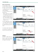
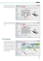
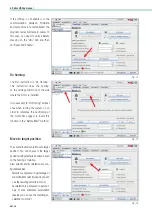
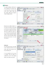
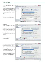
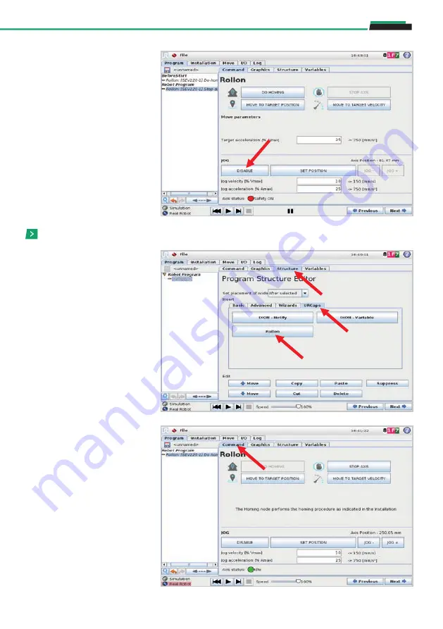
Now move from “Structure” to “Com-
mand”, in the same menu, to set the 
different instructions:

• 

Do homing

• 

Move to target position

• 

Move to target velocity

• 

Stop axis

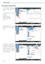
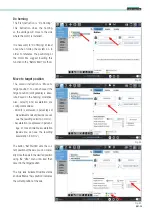
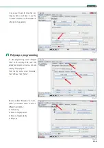
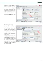
To start programming, select “Program 
robot” on the starting screen and then 
upload your program or create a new one 
clicking “Empty program”. 
From the top menu, select “Structure”, 
then “URCaps”, then “Rollon”. 

Polyscope programming

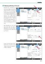
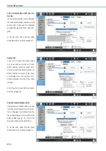
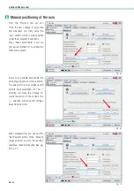
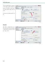
In case you’ll need to move the car-
riage by hand, you’ll have to use the 
“Disable” command (this operation is 
strongly not suggested).

Fig. 71

Fig. 72

Fig. 73

Summary of Contents for ROLLON CTU 220-1I

Page 1: ...Smart System User manual for the Partly Completed Machinery Actuator System Line Cobot Transfer Unit Cobot Transfer Unit for UR cobots...

Page 2: ......

Page 3: ...CTU UM 12 Mounting the robot on CTU UM 13 Connecting CTU UM 14 Connecting the robot UM 16 Air connection Carriage blocking element optional UM 17 Notes on lubrication UM 18 5 Rollon URCap manual e Ser...

Page 4: ...mises direct or final It is therefore understood that the aforementioned operations in points 1 2 and 3 are not chargeable to Rollon Rollon supplies Partly Completed Machinery The client direct or fin...

Page 5: ...than the purpose the system was designed for or derived from failure to comply during incorporation phases with the rules of Good Technique and with what is indicated in this manual To avoid damage do...

Page 6: ...nteed and efficient management of its corporate activities is achieved Within this scope the as in this sense Rollon has identified its management and production processes and designed the sequences a...

Page 7: ...he indications listed below are to ensure correct management of our supply Our products are mainly composed of At the end of the product s life cycle it is therefore possible to recover the various el...

Page 8: ...carried out with vehicles pre senting adequate loading capacity and the machines must anchored to the established points During handling and if required by the conditions have one or more people assis...

Page 9: ...Check axis integrity after shipment Installation Every shipment is accompanied by a document Packing list with the list and description of the axes When a shipment is received check to make sure that...

Page 10: ...x robot power and signal cable The components must be assembled System requirements Power supply 380 480 V power cable supplied with plug IEC 60309 4 pins 3P E UR model CB series robot 3 1 onwards e S...

Page 11: ...idth mm Height mm 500 46 1344 608 662 211 73 1429 736 727 229 99 1458 771 788 231 1000 55 1844 88 1929 114 1958 1500 64 2344 103 2429 133 2458 2000 73 2844 117 2929 150 2958 2500 81 3344 130 3429 167...

Page 12: ...level the entire system Driving head Chains Support chains Motor reduction gear Fixing and levelling crosspiece Robot interface flange Carriage Examples of fixing and levelling crosspieces Fig 3 Fig 4...

Page 13: ...below will give you an idea for positioning the lifting points Please consider them as indications only They are to help explain what is written above The direction of the carriage for programming is...

Page 14: ...ype and property class Fig 8 Fig 9 Anchoring the CTU Leveling screw Fixing screws Fasten both fixing screws Hexagon head bolt with shank UNI 5737 Friction coefficient Tightening torque Nm Property cla...

Page 15: ...n turn anchored to the axis carriage To anchor the robot to the interface flange follow the instructions shown in the robot manual Mounting the robot on CTU Fig 11 Fig 13 Robot power supply connector...

Page 16: ...WHITE cable ethernet It is mandatory to perform any operation of assembly disassembly and cable connection disconnection with the power down Ensure the power is off and the white light is off The elec...

Page 17: ...between the electrical cabinet of CTU and the robot Depending on the order the cables will be supplied in sec tions 3 or 5 meters in length On the cabinet a connector for safety signal is installed e...

Page 18: ...n the order the WHITE cable will be supplied in 6 or 12 meters length The BLUE High Flex robot power and signal cable is already inserted into the cable carrier in the axis chains It is supplied 6m or...

Page 19: ...ig 25 If requested during the order phase the axis comes with clamping elements on the carriage that work on linear rails With this option the carriage presents open sides like the one shown in Fig 23...

Page 20: ...5000 km or once a year whichever quantity is reached first Insert the dispensing nozzle into the specific lubricator Type of lubricant class NLGI 2 lithium soap based grease More frequent lubrication...

Page 21: ...robot must be set in Local mode and not Remote this option is not available for UR3 Press Settings Rollon URCap manual e Series Before you start download the last version of the program Rollon URCap...

Page 22: ...he teach pen dant In the left menu select System then select URCaps and press button Select usbdisk locate the Rollon URCap program and press Open Press Restart and wait for a few seconds 5 Rollon URC...

Page 23: ...tion is not available for UR3 Go to the Installation tab on the top menu select URCaps and then select the correct axis size on the Model pop up menu If flagged deactivate the Enable UR Cap box to pro...

Page 24: ...net configuration the IP configuration will be automatic In case you have 2 cabinets you ll need to set a separate IP address In this case go to the Installation tab of the menu select URCaps and then...

Page 25: ...s will move in accordance with velocity and acceleration set The direction will move the carriage towards the mo tor On the contrary the direction will move the carriage away from the motor When progr...

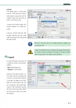
Page 26: ...gram nodes will remain yellow In this case you need to unlock Safety pressing on the UR tab and then on Reset and Enable 5 Rollon URCap manual Go to the Program tab in the top menu In the left menu se...

Page 27: ...e based on the homing or relative Also velocity and acceleration are configurable values Velocity is expressed in percentage of max allowable velocity beside you can see the resulting velocity in mm s...

Page 28: ...percent age of Max allowable acceleration beside you can see the resulting acceleration in mm s2 After Move to target velocity com mand you need to stop the axis before it touches the limit switch sen...

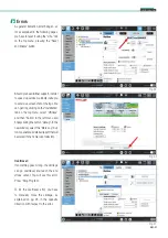
Page 29: ...r as explained in the following pages you have to reset it using the UR tab on the top menu pressing the Reset and Enable button Errors Fig 49 Fig 51 Should you need further support in order to speed...

Page 30: ...oder connection from the cabi net to the motor breaks down or the ca ble is unplugged you will see this error Press Stop Program and switch off the Rollon cabinet see pg 15 This is the only case where...

Page 31: ...nt Email infotec rollon com Telephone 39 039 62591 Should you need further support in order to speed up service we kindly invite you to send us a screenshot of the logs You can get it by clicking on t...

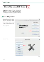
Page 32: ...screen A popup might appear select Not now Press Setup Robot Press URCaps Rollon URCap manual CB Series Before you start download the last version of the program Rollon URCap on our website www rollon...

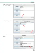
Page 33: ...1 Cobot Transfer Unit Insert your USB key in the teach pen dant and press button Select usbdisk locate the Rollon URCap program and press Open Press Restart and wait for a few seconds Fig 59 Fig 60 Fi...

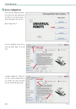
Page 34: ...ht appear select Not now Select Program robot Go to the Installation tab on the top menu and select Rollon on the left menu If flagged deactivate the Enable UR Cap box in order to proceed with the axi...

Page 35: ...g on with the next steps If you only have one CTU in your net configuration the IP configuration will be automatic In case you have 2 cabinets you ll need to set a separate IP address In this case go...

Page 36: ...ual movement Now you can enable and disable the drive pressing plus and minus button The axis will move in accordance with velocity and acceleration set The direction will move the carriage to wards t...

Page 37: ...axis To start programming select Program robot on the starting screen and then upload your program or create a new one clicking Empty program From the top menu select Structure then URCaps then Rollo...

Page 38: ...m nodes will remain yellow In this case you need to unlock Safety pressing on the UR tab and then on Reset and Enable Do homing The second instruction is Move to target position You can choose if the...

Page 39: ...city beside you can see the resulting velocity in mm s Acceleration is expressed in percent age of Max allowable acceleration beside you can see the resulting acceleration in mm s2 Move to target velo...

Page 40: ...es the limit switch sensor Stop axis does just that This symbol indicates a movement in the negative direction towards the motor while this a movement in the positive direction away from the motor The...

Page 41: ...ned in the following pag es you have to reset it using the Jog section which is always visible under the 4 program instructions pressing the Reset and Enable button Errors Fig 81 Fig 83 Should you nee...

Page 42: ...he cabi net to the motor breaks down or the ca ble is unplugged you will see this error Press Stop Program and switch off the Rollon cabinet see pg 15 This is the only case where you ll need to do so...

Page 43: ...al de partment Email infotec rollon com Telephone 39 039 62591 Should you need further support in or der to speed up service we kindly invite you to send us a screenshot of the logs You can get it by...

Page 44: ...UM 42 Notes Notes...

Page 45: ...UM 43 Cobot Transfer Unit Notes...

Page 46: ...UM 44 Notes Notes...

Page 47: ......

Page 48: ...n de www rollon de ROLLON LTD UK Rep Office The Works 6 West Street Olney Buckinghamshire United Kingdom MK46 5 HR Phone 44 0 1234964024 ukandireland rollon com www rollon uk com ROLLON CORP USA 101 B...

Reviews: