UM-14
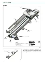
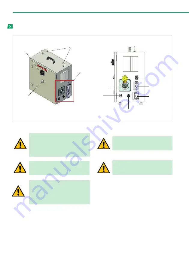
Fig. 15
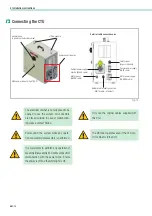
Connecting the CTU
White power indicator light (24 V)
Lifting eyebolts
Detail of cable connection area
Cable connection area
General knob
to power up the Rollon cabinet
Cabinet power supply
electric (BLACK cable)
Motor signal
(GREEN cable)
Safety signal
(bypass installed)
Sensors power supply
(GREY cable)
Motor power supply
(ORANGE cable)
Network cable robot connection
(WHITE cable - ethernet)
It is mandatory to perform any operation of
assembly/disassembly and cable connection/
disconnection with the power down. Ensure
the power is off and the white light is off.
The electrical cabinet is not supposed to be
opened to use the system. All connectors
are placed outside. In case of malfunction-
ing please contact Rollon.
Only use the original cables supplied with
the CTU.
Power down the system while any opera-
tion of assembly/disassembly is performed.
The UR robot operates even if the CTU con-
trol cabinet is turned off.
4 Installation instructions
Summary of Contents for ROLLON CTU 220-1I
Page 2: ......
Page 44: ...UM 42 Notes Notes...
Page 45: ...UM 43 Cobot Transfer Unit Notes...
Page 46: ...UM 44 Notes Notes...
Page 47: ......


