UM-15
Cobot Transfer Unit
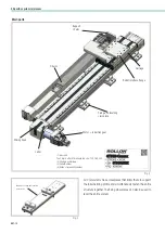
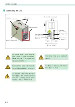
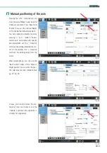
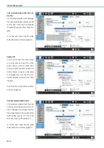
Fig. 17
The
GREY
cable must be plugged into the connector. This will
activate the 3 positioning sensors.
Fig. 16
*
Procedure for connecting electrical cabinet cables:
Cables coming out of the electrical cabinet;
-
ORANGE
cable - motor power,
-
GREEN
cable - motor signals,
-
BLACK
cable - electrical cabinet power supplied with
plug IEC 60309 4 pins 3P + E (380-480V)
-
GREY
cable
-
sensor
power;
- WHITE cable - ethernet connection cable between
the electrical cabinet of CTU and the robot.
Depending on the order the cables will be supplied in sec-
tions 3 or 5 meters in length.
*
On the cabinet a connector for safety signal is installed
(e.g. laser scanner, safety mat, other safety devices, external
safety door).
An external bypass is supplied.
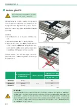
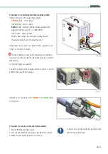
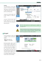
Fig. 18
Indications for connecting the
ORANGE
and
GREEN
cables
to the motor
Procedure for turning on the electrical cabinet:
1. Ensure that the machine is safe;
2. Turn the general knob to power up the electrical cabinet;
3. Make sure the white light (24 V) comes on;
To power up or power down the electrical cabi-
net turn the general knob.
Summary of Contents for ROLLON CTU 220-1I
Page 2: ......
Page 44: ...UM 42 Notes Notes...
Page 45: ...UM 43 Cobot Transfer Unit Notes...
Page 46: ...UM 44 Notes Notes...
Page 47: ......

