background image


S e c u r e   C o n s o l e   S e r v e r   M a n u a l ,   R e v .   K ,   J u l y ,   2 0 1 3  


Page 62 

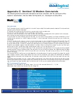
Appendix C: Sentinel 32 Modem Commands 

The following modem commands information has been extracted, with the permission of the 
modem’s manufacturer, from the Multi-Tech Systems, Inc., Developer’s Guide (2003).  


Introduction 

The AT commands are used to control the operation of your modem. They are called AT commands because the characters AT must precede  each 

command to get the ATtention of the modem. 

AT commands can be issued only when the modem is in command mode or online command mode. 

The modem is in command mode whenever it is not connected to another modem. 
The modem is in data mode whenever it is connected to another modem and ready to exchange data. Online command mode is a temporary 
state in which you can issue commands to the modem while connected to another modem. 

To  put  the  modem  into  online  command  mode  from  data  mode,  you  must  issue  an  escape  sequence  (

+++) 

followed  immediately  by  the  AT 

characters  and  the  command,  e.g., 

+++ATH 

to  hang  up  the  modem.  To  return  to  data  mode  from  online  command  mode,  you  must  issue  the 

command 

ATO. 

To send AT commands to the modem you must use a communications program, such as the HyperTerminal applet in Windows 98/ 95 and NT 

4.0, or some other available terminal program. You can issue commands to the modem either directly, by typing them in the terminal window of 

the communications program, or indirectly, by configuring the operating system or communications program to send the commands automatically. 

Fortunately,  communications  programs  make  daily  operation  of  modems  effortless  by  hiding  the  commands  from  the  user.  Most  users, 

therefore, need to use AT commands only when reconfiguring the modem, e.g., to turn auto answer on or off. 

The format for entering an AT command is 

ATXn

where is the command and is the specific value for the command, sometimes called the 

command parameter. The value is always a number. If the value is zero, you can omit it from the command; thus, 

AT&W 

is equivalent to 

AT&W0. 

Most  commands  have  a  default  value,  which  is  the  value  that  is  set  at  the  factory.  The  default  values  are  shown  in  the  “AT  Command 

Summary” (See below). 

You  must  press  ENTER  (it  could  be  some  other  key  depending  on  the  terminal  program)  to  send  the  command  to  the  modem.  Any  time  the 

modem receives a command, it sends a response known as a result code. The most common result codes are OK, ERROR, and the CONNECT 

messages that the modem sends to the computer when it is connecting to another modem. See a table  of  valid  result codes  at  the  end  of  this 

chapter. 

You can issue several commands in one line, in what is called a command string. The command string begins with 

AT 

and ends when you press 

ENTER. Spaces to separate the commands are optional; the command interpreter ignores them. The most familiar command string is the initialization 
string, 
which is used to configure the modem when it is turned on or reset, or when your communications software calls another modem. 

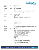
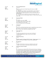
AT Command Summary 

Organization  of  AT  Commands  on  the  following  pages:  1st,  by  the  initial  command  character  (&,  +,  %)  2nd, 

alphabetized by the second command character (Except for listing of 

AT) 


Command 

Description 

AT 

Attention Code 

Answer 

A/ 

Repeat Last Command 

Bn 

Communication Standard Setting 

Ds 

Dial 

DS=y 

Dial Stored Telephone Number 

En 

Echo Command Mode Characters 

Fn 

Echo Online Data Characters 

Hn 

Hook Control 

In 

Information Request 

Mn 

Monitor Speaker Mode 

Nn 

Modulation Handshake 

Summary of Contents for SCS160

Page 1: ...le Servers SCS SCS R and Sentinel Models Product Manual Thinklogical LLC 100 Washington Street Milford Connecticut 06460 U S A Telephone 1 203 647 8700 Fax 1 203 783 9949 www thinklogical com Revision...

Page 2: ...ted in the U S A Thinklogical LLC 100 Washington Street Milford Connecticut 06460 U S A Telephone 1 203 647 8700 All trademarks and services marks are property of their respective owners Appendix C co...

Page 3: ...fe 15 2 3 2 IP Network 15 2 3 3 AC Power 16 2 3 3 1 SCS80 SCS160 SCS320 SCS480 16 2 3 3 2 SCS80R SCS160R SCS320R Sentinel 32 16 2 3 3 3 SCS480R 16 2 3 4 DC Power 16 2 4 User Access Control 16 2 4 1 Us...

Page 4: ...Interface 35 5 System Overview 35 5 1 SCS Systems are Linux based 35 5 1 1 Linux General Public License 35 5 1 2 SCS System Architecture 35 5 2 Initial System Administrator sysadmin Access 36 5 2 1 En...

Page 5: ...ser Setup 51 8 1 1 adduser 51 8 1 2 edituser 52 8 1 3 deluser 52 8 1 4 Other Editing Commands 52 8 1 4 1 editbrk name 52 8 1 4 2 editesc name 52 9 User Operations 52 9 1 User Accounts 52 9 1 1 SCS use...

Page 6: ...s and Sentinel 32 Power Modules 57 11 How to Contact Us 57 11 1 Customer Support 57 11 1 1 Website 57 11 1 2 E mail 58 11 1 3 Telephone 58 11 1 4 Fax 58 11 2 Product Support 58 11 2 1 Limited Warranty...

Page 7: ...rnings appear in red text preceded by a red stop sign as shown here A warning is meant to call the reader s attention to critical information at a point in the text that is relevant to the subject bei...

Page 8: ...er SCS480 48 Port 1U Secure Console Server The SCS80R SCS160R SCS320R and SCS480R models are designed with dual hot swappable Power Modules which operate redundantly and two network ports and console...

Page 9: ...are shipped with regionally appropriate power cord sets Otherwise each international model is similar to the domestic SCS80 SCS160 SCS320 SCS480 SCS80R SCS160R SCS320R SCS480R and Sentinel 32 models...

Page 10: ...with network administrators in mind No special administration tools training or procedures required You know Linux we run Linux Open source Linux Operating System Red Hat compatible Proprietary SCS fe...

Page 11: ...SCS80R SCS160R and SCS320R Hardware The SCS80R SCS160R and SCS320R models offer hardware redundancy for power network and console ports Features include dual NIC inputs dual console port inputs and ho...

Page 12: ...8 conductor connector one DTE one DCE Software selectable data rate from 300 115K Baud Software selectable EIA 232 parameters Network interface Network 80 160 320 480 10 100 BaseT RJ45 8 conductor Et...

Page 13: ...s switches etc They do so by monitoring the console port of your network center s devices and systems Each attached component must have an EIA 232 compatible serial port The SCS80 and SCS80R support 8...

Page 14: ...and protective fuse located on the rear of the chassis of the SCS80R SCS160R and SCS320R located on the front of the chassis of the SCS480R Each Power Module is secured with a captive mounting screw 2...

Page 15: ...m ports numbered from 1 to up to 48 are default configured as DCE data ports and support a range of baud rates from 300 115 2K All Port parameters including DTE or DCE type and other data parameters a...

Page 16: ...cord sets to a standard AC power source Turn both power switches ON l Warning Turn the module POWER OFF and remove its power cord BEFORE removing a power module A hazardous voltage condition might oth...

Page 17: ...nds See the man page for stty buffer option 3 Installation 3 1 Mounting the SCS You may choose to rack mount your SCS unit or place it on a desktop The front panel display should be visible and front...

Page 18: ...does not require special cooling or ventilation other than what is normally provided in a standard equipment rack No fan means that it does not add to the ambient noise in your equipment room Be sure...

Page 19: ...Replace with same type and rating fuse 100 240V 0 5A 50 60 Hz T2A 250 VAC CAUTION Replace with same type and rating fuse 100 240V 0 5A 50 60 Hz T2A 250 VAC CAUTION Replace with same type and rating f...

Page 20: ...roperly grounded 3 2 3 Connecting to the Network Port Use a conventional fully pinned Category 5 cable CAT5 to connect your network to the NETWORK RJ45 jack on the rear of the chassis The SCS s networ...

Page 21: ...SCS the login as prompt will appear Log in as root Press Enter to continue The password prompt comes up next Enter root the default root password and press Enter 3 2 4 1 SCS R and Sentinel 32 Dual Con...

Page 22: ...utomated Port Configuration Tests A script named pm is available to test the device ports and report the correct DTE DCE setting for each port A man page exists for pm This can be used to troubleshoot...

Page 23: ...move the AC power cord from the SCS480R when replacing a module Note The Power Modules in the SCS160 320 480 are not field serviceable This option applies to the SCS80R SCS160R SCS320R SCS480R and Sen...

Page 24: ...the SCS480R chassis holds the Power Module in place and also establishes a protective Earth ground Be sure to turn off the failed power module press switch to O position It is not necessary to remove...

Page 25: ...n is to have two power sources running your SCS system When both supplies are active they will share the system load If one fails the remaining supply can then take the full load The SCS80R SCS160R SC...

Page 26: ...h ground Be certain to turn off the failed power module press switch to O position then remove its power cord connection Unscrew the module and remove it from the chassis using the built in handle SCS...

Page 27: ...hen you first connect the SCS and turn it on it will build the ssh keys during the first two minutes of system startup During this time the front panel LCD second line will read start sshd and the con...

Page 28: ...ancel your new changes If you do not Save your settings at this time your new changes will be discarded Note Front panel changes are not written to the Compact Flash memory until the sysadmin uses the...

Page 29: ...de To change the IP Address press the Enter button SCS Front Panel Display showing Edit IP Address A cursor appears under the first character of the existing address Press the Left or Right arrow butt...

Page 30: ...will be displayed with a cursor under the first digit The factory default is 255 000 000 000 Press the Left or Right arrow button to move the cursor to the first digit to be changed To change a digit...

Page 31: ...he Left or Right arrow button to move the cursor to the first digit to be changed To change a digit use the Up or Down arrows As soon as you change a digit an asterisk will appear at the top right ind...

Page 32: ...work Daemon The Network Daemon periodically connects to the network to check for updates and notifications This process will be displayed on the front panel display The display will revert to a normal...

Page 33: ...first changes you make is to your SCS s network address See Section 7 2 Change Network Address on page 41 4 4 3 Route via Windows Workstation If using a Linux workstation you may skip this section If...

Page 34: ...u connect using ssh you will get a warning about the ssh authentication keys Accept the newly generated keys by choosing yes 5 Login to the SCS When connected to the SCS the login as prompt will appea...

Page 35: ...ess the device ports To disable the web interface see the instructions located in lsi README 5 System Overview 5 1 SCS Systems are Linux based Thinklogical Secure Console Server products use the GNU L...

Page 36: ...disconnect the ssh session 5 3 Default Services The following Services are enabled by default network ssh syslog cron You may add other features and services depending on your application When you fi...

Page 37: ...config changehostname timeconfig authconfig 2 Run save 3 Run service network restart to restart the network To configure the existing features use the following commands For the Network parameters use...

Page 38: ...wer is applied and the system remains in a normal operating condition To permanently store your parameters the root user must use the save command to write the data changes to the non volatile Compact...

Page 39: ...he front panel display will show OK to Power Off You may now turn the power switch off The only way to recover from a poweroff command is to turn the system power off and then turn the power back on 6...

Page 40: ...r users so passwords do not have to be used for ssh login You can generate the security keys for your client system in this case the SCS is the client to interact with an ssh host elsewhere After the...

Page 41: ...ffers or clear the buffered data 7 2 Change Network Address You may use the Front Panel setup see Section 4 3 Front Panel Network Setup beginning on page 27 to configure the SCS s IP address This will...

Page 42: ...to the root prompt See Section 7 2 2 More Than One Nameserver on page 43 7 2 1 1 Save your netconfig changes After running netconfig to set up your system you must run the save command to keep your c...

Page 43: ...stname Note If you make a mistake in your entry do not attempt to edit it Reject the incorrect entry and re enter the value properly 4 Enter your new hostname value Press y to accept the new value 5 R...

Page 44: ...uthconfig to set up the authentication protocols You may only need to run this if you need remote authentication such as NIS LDAP Kerberos etc The first checkbox cache information will start the nscd...

Page 45: ...splay to show the current display information and allows anyone to use the front panel display to change the network parameters IP Address Net Mask and Gateway 7 7 1 2 View The View mode LCD_DISPLAY V...

Page 46: ...e file Example For the hostname ts1 mydomain your entry is server ts1 mydomain The user will type the actual hostname or IP address of the time server in place of ts1 mydomain The user should also add...

Page 47: ...group can connect with monitor perm are the ports that a group can monitor clear perm are the ports that a group is allowed to clear For example pbxgrp tvscs320 1 2 6 13 5 9 1 7 itgrp tvscs160 8 16 7...

Page 48: ...names are defined below Users must be valid system usernames Group names are those defined in the lsi_port_access file lsiuser1 user_group1 lsiuser2 user_group1 lsiuser3 user_group2 lsiuser4 user_gro...

Page 49: ...1 Remote NFS Directory To mount a remote directory onto the SCS you must start the portmap and netfs services To manually start portmap and netfs services enter the commands service portmap start ser...

Page 50: ...vel events User settings modified Port buffer accessed The default file entry is notice with lower level settings in info A lower level setting generates more messages 7 13 Timeouts The SCS system sup...

Page 51: ...e above valid port numbers for that chassis 1 4 7 12 15 16 ESCAPE_SEQ Escape sequence Default is Esc A Displayed in ASCII x1bA BREAK_SEQ Break sequence Default is Esc B Displayed in ASCII x1bB ALLOW_C...

Page 52: ...oke default is ESC B 8 1 4 2 editesc name Use editesc name to edit the escape sequence for a user The escape sequence is presented in its ASCII form User key stroke default is ESC A 9 User Operations...

Page 53: ...Administrator during service events However it can be used by any user that has access to the terminal and has a password to log into the system and access system Ports 9 3 3 Interactive Mode For a u...

Page 54: ...nter editesc to edit or view the preset escape sequence The escape sequence is presented in its ASCII form x1bA The user key stroke default is ESC A Press Enter to keep the existing setting Warning Be...

Page 55: ...15 Class A Industry Canada ICES 003 Issue 2 Revision 1 10 2 2 European Union 10 2 2 1 Declaration of Conformity Product name Model SCS80 Secure Console Server SCS801 Secure Console Server Model SCS16...

Page 56: ...ccordance with the instruction manual may cause harmful interference to radio communications in which case the user may be required to correct the interference Note This Class A digital apparatus comp...

Page 57: ...en replacing a Power Module in the field first turn the power switch off then remove the Power Cord BEFORE loosening the captive screw and pulling the module out When replacing the module fully insert...

Page 58: ...ach you at your convenience Our switchboard attendant will direct your call during regular business hours We have an automated attendant after regular business hours and on holidays Please leave a voi...

Page 59: ...lusive remedies for a breach of the limited warranty set forth above To return a defective product contact the Thinklogical authorized dealer from whom you purchased the product Do not return a produc...

Page 60: ...ould shorten the life span of the SCS The SCS s file system is normally mounted in a read only mode and is run from RAM to prolong the life read write cycles of the system s Compact Flash memory card...

Page 61: ...Changing port names is persistent over a reboot Changing port communication settings baud rate parity etc is temporary The file etc rc serial must be edited in order to save the settings To change th...

Page 62: ...e user Most users therefore need to use AT commands only when reconfiguring the modem e g to turn auto answer on or off The format for entering an AT command is ATXn where X is the command and n is th...

Page 63: ...ications Mode Sn Data Set Ready DSR Control Tn Loopback Test V 54 Test Commands V Display Current Settings Wn Store Current Configuration Zy x Store Dialing Command An Select Maximum MNP Block Size Bn...

Page 64: ...AT Do not press ENTER to execute Command Bn Communication Standard Setting Values n 0 3 15 16 Default 0 and 15 Description B0 Select ITU T V 22 mode when modem is at 1200 bps B1 Select Bell 212A when...

Page 65: ...1 F0 Enable online data character echo Not supported F1 Disable online data character echo included for backward compatibility with some software Command Hn Hook Control Values n 0 or 1 Default 0 Des...

Page 66: ...rns an OK for backward compatibility with some software Command Sr n Set Register Value Values r S register number n varies Default None Description Set value of register Sr to value of n where n is e...

Page 67: ...OFF when the carrier signal is not detected C2 DCD turns OFF upon disconnect for time set by S18 It then goes high again for some PBX phone systems Command Dn Data Terminal Ready DTR Control Values n...

Page 68: ...buffering Same as N3 Q6 Asynchronous with data buffering Same as N0 Q8 MNP error control mode If MNP error control is not established the modem falls back according to the setting in S36 Q9 V 42 or MN...

Page 69: ...0 9 in 100 ms units Default 3 Description In non error correction mode only sends a break signal of the specified length to a remote modem Works in conjunction with the K command Command Kn Break Con...

Page 70: ...Note You can also set the inactivity timer by changing the value of S30 Command Vn Protocol Result Code Values n 0 1 or 2 Default 1 Description V0 Disables the appending of the protocol result code to...

Page 71: ...Disable fallback and fall forward E1 Enable fallback disable fall forward E2 Enable fallback and fall forward Command Hn Direct Connect Enable Values n 0 1 Default 0 Description H0 Sets callback secu...

Page 72: ...serial port to 4800 bps SB9600 Sets serial port to 9600 bps SB1 9200 Sets serial port to 19200 bps SB38400 Sets serial port to 38400 bps SB57600 Sets serial port to 57600 bps SB1 15200 Sets serial po...

Page 73: ...la tile memory Command CBIn Local Callback Inactivity Timer Values n 1 255 Default 20 Description Sets the time in minutes that the modem waits for a command before forcing the user to enter the setup...

Page 74: ...er is defined in register S13 V 92 Commands Command MS Modulation Selection Values See description Defaults See description Description This extended format command selects modulation enables or disab...

Page 75: ...Enable automode default max_rate An optional number that specifies the highest rate at which the modem may establish an upstream transmit connection The value is decimal coded in units of bps for exam...

Page 76: ...em Hook Flash Values n a Default n a Description Causes the DCE to go on hook for a specified period of time and then return off hook for at least a specified period of time The specified period of ti...

Page 77: ...ble to disable quick connect PQC 0 Enables Short Phase 1 and Short Phase 2 Quick Connect PQC 1 Enables Short Phase 1 PQC 2 Enables Short Phase 2 PQC 3 Disables Short Phase 1 and Short Phase 2 PQC Disp...

Page 78: ...e reset or power up This number can be stored to nonvolatile memory using the W command Command CBFR Callback Failed Attempts Reset Values n a Default n a Description Resets the number of failed callb...

Page 79: ...the carriage return character S4 decimal 0 127 10 J Sets the ASCII code for the line feed character S5 decimal 0 32 8 H Sets the ASCII code for the backspace character 33 1 27 Values greater than 32 d...

Page 80: ...6 bps 23 56 000 bps Upstream data rates Upstream V 90 data rates are 4800 to 33 600 bps in 2400 bps increments S43 decimal 0 1 1For testing and debugging only Enables disables V 32bis start up auto mo...

Page 81: ...nnected at 2400 bps 11 CONNECT 4800 Connected at 4800 bps 12 CONNECT 9600 Connected at 9600 bps 13 CONNECT 14400 Connected at 14400 bps 14 CONNECT 19200 Connected at 19200 bps 18 CONNECT 57600 Connect...

Page 82: ...107 CONNECT 41333 Connected at 41333 bps 108 CONNECT 42666 Connected at 42666 bps 109 CONNECT 45333 Connected at 45333 bps 110 CONNECT 46666 Connected at 46666 bps 111 CONNECT 49333 Connected at 4933...

Page 83: ...81 VW 1 compliant equivalent 16 AWG three wire set 48V Power Supply Ground and Common 3 Strip 0 35 inches 9 mm of installation from each wire 4 Insert a small flat blade screwdriver one at a time into...

Page 84: ...protection requirements 10 Amp fast trip Double pole DC rated Over current protection devices e g circuit breakers must be provided as part of each equipment rack and are not included with the Consol...

Page 85: ...r To do this modify the openSSH server code The SCS ships with the original ssh code installed and running Several steps are taken to use the modified ssh program and to assign addresses to the device...

Page 86: ...r M a n u a l R e v K J u l y 2 0 1 3 Page 86 1 2 3 4 5 6 7 8 RJ45 ADP 000005 RJ45 to 25 pin Male 4 20 2 7 3 6 5 RJ 45 25 pin 1 8 ADP 000006 RJ45 to 25 pin Female Wire key 1 Blue 2 Orange 3 Black 4 R...

Page 87: ...l R e v K J u l y 2 0 1 3 Page 87 1 2 3 4 5 6 7 8 RJ 45 RJ 45 Jack Pin1 ADP 000007 R DB9 Male 7 4 3 5 2 6 8 ADP 000007 R RJ45 to DB9 Male DB9 ADP 000008 R RJ45 to DB9 Female Wire key 1 Blue 2 Orange...

Page 88: ...r M a n u a l R e v K J u l y 2 0 1 3 Page 88 1 2 3 4 5 6 7 8 RJ45 ADP 000009 RJ45 to 25 pin Male 4 20 2 7 3 6 8 5 RJ 45 25 pin 1 8 ADP 000010 RJ45 to 25 pin Female Wire key 1 Blue 2 Orange 3 Black 4...

Page 89: ...l R e v K J u l y 2 0 1 3 Page 89 1 2 3 4 5 6 7 8 RJ 45 RJ 45 Jack Pin1 ADP 000011 R DB9 Male 7 4 3 5 2 1 6 8 ADP 000011 R RJ45 to DB9 Male DB9 ADP 000012 R RJ45 to DB9 Female Wire key 1 Blue 2 Orange...

Page 90: ...S e c u r e C o n s o l e S e r v e r M a n u a l R e v K J u l y 2 0 1 3 Page 90 Appendix G Quick Start Guide...

Reviews: