Software control: Microscope Control
3-27
C O N F I D E N T I A L
– limited rights
User Manual
Revision A
Feb 2018
Imaging area
The Microscope Control software (UI) uses 4 independent displays for imaging samples. Each display can contain
images from any detector (including External and CCD), paused imaging or images loaded from a file. Additionally,
display 3 can show a mix of images from displays 1 and 2, and display 4 can show a mix of images from displays 1,
2 and 3.
The Quad image and Single image modes are available. The
Quad Image
mode shows 4 displays at the same time.
The
Single Image
mode shows one display over the UI imaging area.
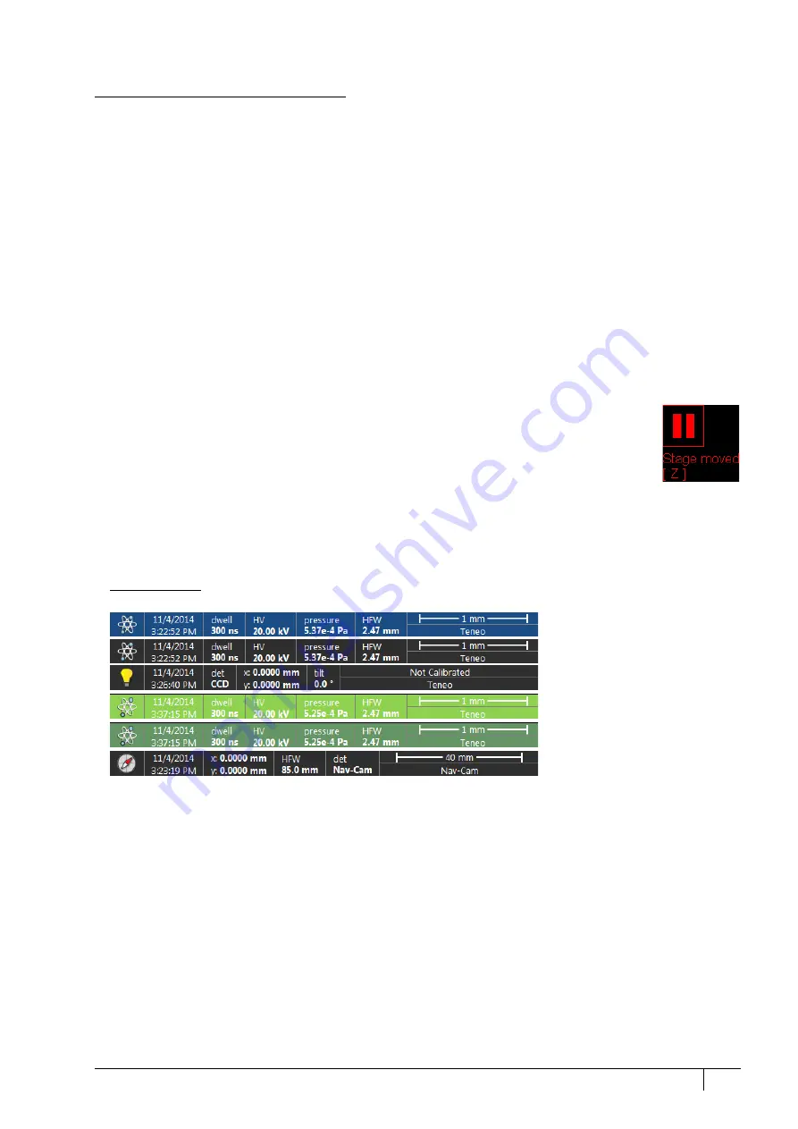
Each display consists of its imaging area, an adjustable Databar containing the imaging parameters, a selectable
overlay (user-defined coloring, annotations, measurements) and some status icons (Pause, Sample Navigation,
etc.).
At any one time, just one display is active (has focus), and all functions related to it (Pause, Sample Navigation,
image processing) apply only to imaging on this display. The active display is marked by the highlighted (blue
background) Databar and optionally also by a blue frame (see
Preferences / General
).
Depending on the display content and the status, some mouse functions are available over its area:
•
Electron imaging
(incl. External and Mix): focus, astigmatism correction, Beam Shift, magnification change
(coarse, fine), zoom (in / out), Contrast & Brightness, lens alignment, Scan / Compucentric Rotation, XY-move
(get or track mode)
•
Optical imaging
: 10 mm Marker placement, Compucentric Rotation, Z-move (track), Tilt, Working distance
indicator
Optical imaging is automatically activated (if it is paused) when the venting procedure starts.
When it is paused and any stage movement takes place, the pause icon turns red, and a list of
changed axes is shown.
Note
Due to hardware limitations, some detectors cannot be used simultaneously. They can still be selected
for different displays at the same time, but if one of them is started, other imaging with the incompatible
detector is automatically paused.
Image databar
Optional instrument, imaging and labeling information are shown at the base of all displays. The configuration and
available items differ for the beam selected (Electron / Optical / Nav-Cam) for the active display.
FIGURE 3-13:
Databar examples
Note
The Databar information always relates to the live imaging. If imaging is paused or an image is loaded from a file, the
information can differ from what is in the actual system conditions.
Active electron display
Inactive electron display
Inactive optical display
Active Patterning display
Inactive Patterning display
Inactive Nav-Cam display (option)


