Operating Procedures: Beam Deceleration
5-22
User Manual
C O N F I D E N T I A L –
limited rights
Feb 2018
Revision A
Applications
The Beam Deceleration mode provides the following features:
•
Enables detection of the BSE when the electron energy is under the detection limit of the detector.
•
Expands the electron energy range under the minimum HV limit.
•
Improves the microscope resolution at low accelerating voltages. A conventional microscope resolution is
limited by chromatic aberrations at low electron energies. The higher the Immersion Ratio, the smaller are the
aberrations and a loss of resolution at low electron energies is well compensated.
•
Enables detecting of electrons heading nearly parallel to a surface, which accentuates surface roughness.
Restrictions
In the LoVac mode, the chamber environment is rather electrically conductive, and the BDM is not available.
Sample preparation and limitations
In general, all types of samples can be imaged using the Beam Deceleration mode. However, there are several types
with certain limitations that should be mentioned:
•
Tilted samples
Tilted samples, such as non-horizontal fractures, may cause distortion of the electrical field deformation, which
adds non correctable aberrations and an image distortion. In general, the flatter the sample the better for the
resolution and also ease of use (fewer corrections of astigmatism and lens alignments).
An acceptable sample tilt is about a few degrees; for higher immersion ratios, it is preferably less.
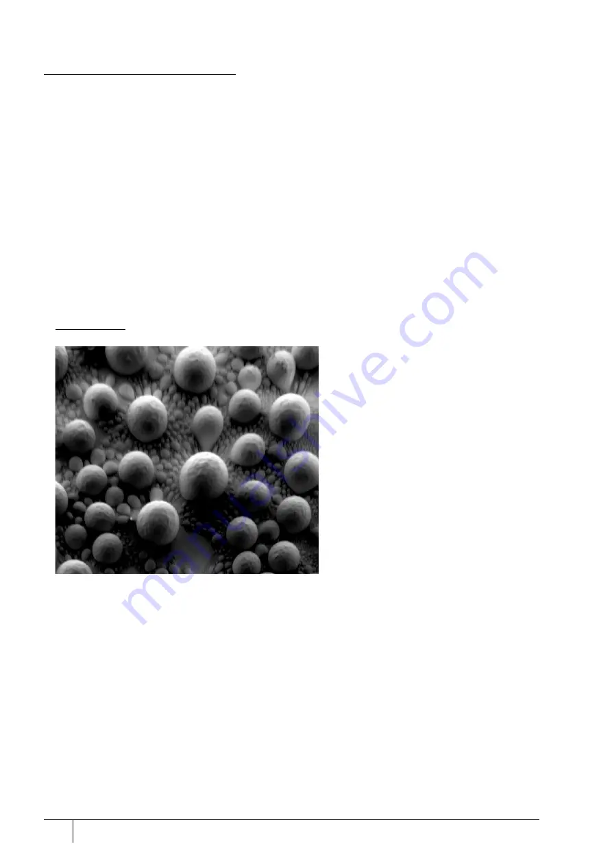
FIGURE 5-9:
Signal Distortion and Image Aberrations for Tilted and Rough Sample (Tin balls) at high Immersion Ratio
•
Particulate samples
All samples consisting of small (micro- or nano-particles) particles must be prepared to minimize presence of
volatile particles on the stub when loaded into the chamber. The sample can be prepared either from solution
(dilute the powder in ethanol or isopropylalcohol, disperse and put few droplets on a clean stub or piece of
wafer) or fixed by carbon paste or tape. When pumping and venting, keep the sample at long working distance
(10 mm) and ideally off the pole piece. Imaging can be done on any working distance.
For the systems with T1 detector, the shortest working distances are interlocked by the software.
•
Non-conductive particles, fibers, wires and rods
These samples are very sensitive to charging induced by an electron beam. When charged, they have tendency
to be attracted by the electric field of the Beam Deceleration, and move around the stub or travel towards the
final lens pole piece. Therefore, these samples have to be securely fixed to the stub. Longer working distance or
lower Stage bias is another way that prevents the column from the particle contamination. Decreasing of a
sample exposition to the electron beam (by setting of low voltage, low current and short dwell time) is
recommended.
C a u t i o n !
Always use a dust off, compressed air or nitrogen to blow all loose particles from the stub / sample before inserting into
the microscope chamber!


