77
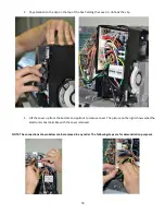
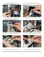
4.
Disconnect the transformer secondary
connector from the PCB board.
5.
Disconnect the (white) horizontal louver connector.
6.
Disconnect the power, signal, and ground wires
going to the top of the terminal block.
7.
Disconnect the transformer primary connector.
8.
Disconnect the (CN3) evaporator coil sensor.
9.
Disconnect the (CN1) ambient temperature sensor.
10.
Disconnect the indoor fan motor connector.
11.
Disconnect the indoor fan signal connector.
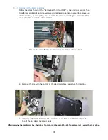
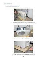
After all connectors are disconnected, PCB can be removed. To install new PCB, reconnect all the connectors to new PCB.
Summary of Contents for 12H47YIMI
Page 10: ...10 1080 mm 226 mm 335 mm 30H48ZIMI 49 57 1259 mm 11 1 282 mm 14 25 362 mm 36H46ZIMI...
Page 19: ...19 Model Voltage V Capacity BTU Type 12H47ZOMI 230 12 000 HEAT PUMP...
Page 56: ...56 P W N U...
Page 57: ...57 N V N W...
Page 82: ...82 7 Then lift the PCB assembly off the unit NOTE All wires are still connected...


