background image

PROVIDENCE INSERT

PELLET STOVE

37

FIGURE 18 - ELECTRICAL SCHEMATIC/WIRING DIAGRAM

Summary of Contents for providence

Page 1: ...IALS ABOUT RESTRICTIONS AND INSTALLATION INSPECTION AND PERMIT FAILURE TO COMPLY WITH OWNER S MANUAL INSTRUCTIONS AND INSTALLATION GUIDELINES WILL VOID WARRANTY SAVE THESE INSTRUCTIONS Made in the USA...

Page 2: ...High Temp Flue Indicator 23 Igniter Location 33 Installation 9 Installed as Built In 13 Laboratory Listing Label 6 Lighting Instructions 21 Maintenance Procedures 24 Masonry Fireplace Installation 9 M...

Page 3: ...Venting Horizontal 15 Figure 7 Pipe Adapter Hook Up 16 Figure 8 Adjustable Hopper 17 Figure 9 Control Panel 17 Figure 10 Air Shutter 18 Figure 11 Surround Installation 19 Figure 12 Control Functions...

Page 4: ...e Over firing or any such action that may cause a fire hazard including failure to perform regular maintenance as outlined in these instructions will void warranty DO NOT store or use gasoline or othe...

Page 5: ...nd followed 2 The Owner s Manual has been read 3 Floor protection requirements have been adhered to 4 All venting has been properly installed 5 The proper clearances from the stove and chimney to comb...

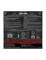
Page 6: ...PROVIDENCE INSERT PELLET STOVE 6 LABORATORY LISTING LABEL...

Page 7: ...ted and will void your warranty and or could cause a burn back or house fire FOR BEST RESULTS THE WOOD PELLET FUEL SHOULD BE DIAMETER AND APPROXIMATELY 1 LONG Store fuel in a covered dry area Pellet b...

Page 8: ...PROVIDENCE INSERT PELLET STOVE 8 FIGURE 1 STOVE DIMENSIONS...

Page 9: ...kways Distance to bottom of termination cap and grade should be 12 Grade surface must be non combustible material such as rock dirt gravel Beware of plants lawn bushes and shrubs which are considered...

Page 10: ...lled to seal the damper area with clearance hole to allow exhaust vent pipe to pass through Use non flammable insulation to seal edges and to prevent heat loss H Aluminum flex pipe can be used to brin...

Page 11: ...f 25 F Pellet vent connections must be sealed with a liberal amount of 500 degree HIGH TEMP RTV silicone and screwed together with at least 3 sheet metal screws G Pellet vent exhaust vent termination...

Page 12: ...PROVIDENCE INSERT PELLET STOVE 12 FIGURE 2 CLEARANCES Factory Built Metal and Masonry Fireplaces Minimum opening for Factory Built Metal and Masonry Fireplaces...

Page 13: ...PROVIDENCE INSERT PELLET STOVE 13 FIGURES 3A D FACTORY BUILT METAL OR MASONRY FIREPLACE VENTING 3A Vertical vent without outside air 3B Vertical vent with outside air options...

Page 14: ...ll the stove on the side of the house that is hit by prevailing winds usually 30 to 40 mph or greater there is a chance that the sensor will be activated and the stove will shut off The solution to th...

Page 15: ...per Figure 4 B Horizontal Installation A minimum 2 ft Type L 4 pipe vertical rise is required with a 2 ft maximum horizontal run to the outside Vertical Installation A maximum vertical rise of 25ft us...

Page 16: ...e is flush with the finished material 3 Install wall thimble with outside air hook up into wall or chase if applicable see Figures 5 6 Outside air is only required on mobile home installations 4 Attac...

Page 17: ...draft blocked flue or high temperature condition If you install the stove on the side of the house that is hit by prevailing winds usually 30 to 40 mph or greater there is a chance that the sensor wil...

Page 18: ...OK UP 1 Silicone the top of flue flange with 500 degree HIGH TEMP RTV silicone and insert flex liner or 4 pipe Fasten pipe or flex liner with at least 3 sheet metal screws 2 Silicone the flue gasket t...

Page 19: ...PROVIDENCE INSERT PELLET STOVE 19 FIGURE 8 ADJUSTABLE HOPPER ASSEMBLY...

Page 20: ...PROVIDENCE INSERT PELLET STOVE 20 FIGURE 9 CONTROL PANEL...

Page 21: ...azy Dark flames smoke or black tips on the flame is an indication of too little air If the flue configuration is tall over 15 feet the shutter should be closed more than a shorter vent since the highe...

Page 22: ...lining up the bottom previously loosened L mount brackets with the surround s predrilled holes 3 Then move hopper flange previously loosened and mate to the underside of top inside of the surround all...

Page 23: ...feet minimum above grade when located adjacent to public walkways Distance to bottom of termination cap and grade should be 12 Grade surface must be non combustible material such as rock dirt gravel...

Page 24: ...ord is connected both into stove connector under control box on right side and into wall outlet Fill hopper with pellets Capacity of hopper can be adjusted depending upon fireplace opening dimensions...

Page 25: ...ED HIGH and CLEAN see Figure 12 A In the LOW position the PROVIDENCE will feed approximately 2 pounds of pellets per hour Feed rate will depend upon size and quality of pellets and the feed trim setti...

Page 26: ...nt To the left of the Medium button there is a small control knob that will allow you to adjust the feed rate on all three settings If you turn the knob clockwise you will increase the feed rate If yo...

Page 27: ...ttery terminals touch stove Failure to install correctly could cause physical harm and short out circuit board and will void the warranty on the heater When the battery is properly connected the follo...

Page 28: ...type of pellet b Ash and clinker build up in the firepot will affect the quality of burn and can cause ignition issues More frequent cleaning may be necessary with poor quality or high ash fuel Weekl...

Page 29: ...t build up is present Build up on the feed chute will prevent pellets from falling freely into the firepot 4 Remove clean out cover on bottom of the tee outside if applicable and dump excess ash from...

Page 30: ...be fully sealed with silicone having a temperature rating of at least 500 degrees F k Vacuum stove cabinet and ducts to remove any accumulated dust fuzz or pet hair 3 Venting system a Clean flue venti...

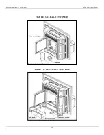
Page 31: ...PROVIDENCE INSERT PELLET STOVE 31 FIGURE 13 CLEAN OUT COVERS FIGURE 14 CLEAN OUT VENT PORT...

Page 32: ...PROVIDENCE INSERT PELLET STOVE 32 FIGURE 15 COMBUSTION FAN...

Page 33: ...he heater was lit and burning properly then suddenly it stopped feeding pellets Solution Check pellet supply in hopper and fill if empty Occasionally a foreign object debris excessive sawdust or even...

Page 34: ...or whining then the bearing might be bad and it is time for a new fan motor 6 Problem Stove shuts off by itself when running on low Solution Feed trim button is too low for the pellets you are using...

Page 35: ...NCE INSERT PELLET STOVE 35 FIGURE 16 REPLACEMENT PARTS LIST 5 1 2 3 4 6 7 8 9 1 Fan assembly 2 Fan gasket 3 Feed motor assembly 4 Feed gasket 5 Igniter 6 T1 sensor 7 T2 sensor 8 Circuit board 9 Switch...

Page 36: ...PROVIDENCE INSERT PELLET STOVE 36 FIGURE 17 CIRCUIT BOARD DIAGRAM Type 2 Low High Thermostat Type 1 On Off Thermostat 17 0...

Page 37: ...PROVIDENCE INSERT PELLET STOVE 37 FIGURE 18 ELECTRICAL SCHEMATIC WIRING DIAGRAM...

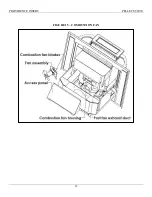
Page 38: ...acket holding the igniter is attached to the lid with two 10 32 nuts The lid attaches to the air chamber with two 10 32 nuts Also a gasket not shown is installed between the lid and the air chamber 2...

Page 39: ...ial damages so the above limitation or exclusion may not apply to you This warranty gives you specific legal rights that vary from state to state WARRANTY WORK If you find this unit to be defective in...

Page 40: ...PROVIDENCE INSERT PELLET STOVE THELIN HEARTH PRODUCTS 63 Laxalt Dr Carson City NV 89706...

Page 41: ......

Reviews: