PROVIDENCE INSERT
PELLET STOVE
38
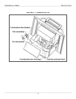
FIGURE 19 - IGNITER LOCATION
1. The bracket holding the igniter is attached to the lid with two 10-32 nuts. The lid attaches to the air
chamber with two 10-32 nuts. Also, a gasket (not shown), is installed between the lid and the air
chamber.
2. Unscrew the igniter element from tube to replace.
Remove
nuts
Unscrews
Summary of Contents for providence
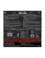
Page 6: ...PROVIDENCE INSERT PELLET STOVE 6 LABORATORY LISTING LABEL...
Page 8: ...PROVIDENCE INSERT PELLET STOVE 8 FIGURE 1 STOVE DIMENSIONS...
Page 19: ...PROVIDENCE INSERT PELLET STOVE 19 FIGURE 8 ADJUSTABLE HOPPER ASSEMBLY...
Page 20: ...PROVIDENCE INSERT PELLET STOVE 20 FIGURE 9 CONTROL PANEL...
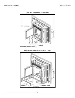
Page 31: ...PROVIDENCE INSERT PELLET STOVE 31 FIGURE 13 CLEAN OUT COVERS FIGURE 14 CLEAN OUT VENT PORT...
Page 32: ...PROVIDENCE INSERT PELLET STOVE 32 FIGURE 15 COMBUSTION FAN...
Page 37: ...PROVIDENCE INSERT PELLET STOVE 37 FIGURE 18 ELECTRICAL SCHEMATIC WIRING DIAGRAM...
Page 40: ...PROVIDENCE INSERT PELLET STOVE THELIN HEARTH PRODUCTS 63 Laxalt Dr Carson City NV 89706...
Page 41: ......


