


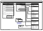


0 ON-DEMAND
Functions Activated
by Pressing the
PROGRAM Button
1 Calibration
Procedures
2 Related Calibration
Functions
3 -
0 No function
1 On Demand TARE from the
PROGRAM button
2 On Demand Single-point
Calibration from the PROGRAM
button (requires single input
source)
3 On Demand 2-point Calibration
from the PROGRAM button
(requires dual input source)
4 On Demand Primary Input
Compensation Mode from the
PROGRAM button
5 On Demand Manual Loader
Mode (no increase / decrease
with HOLD active)
6 -
7 -
Note:
When in the TARE mode, a deci-
mal point appears at the right of
the display indicating that the tare
value is NOT zero.
6
2 February, 2005 Code Sheet V4.01d (NZ1001)
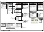
CALIBRATION MODES FOR INPUT AND OUTPUT
FIRST DIGIT
SECOND DIGIT
See Page 7 for a breakdown of
the sub-menu
Use buttons
to set SPAN
Press the PROGRAM button for 4 seconds to
tare
the selected channel
4 secs
4 secs
Use buttons
to set ZERO
Use buttons
to set SPAN
4 secs
Use
buttons to ADJUST primary input
compensation value from –199999 to 999999
Use
buttons to ADJUST the value on the selected channel
from –199999 to 999999 via the manual loader output. See Note*
4 secs
4 secs
Press the PROGRAM button for 4 seconds to
display
the single-point calibration settings
When all 3 digits are selected and the meter is running in the operational display, press
the
button for 4 seconds to
activate
the selected on-demand function
Use buttons
to set SCALE
Use
buttons to set
OFFSET
Use buttons
to set ZERO
Use buttons
to set SPAN
All smart input modules have individual calibration procedures.
See the specific smart input module data sheet for setup procedures
Use buttons
to set CAL_LO
Use buttons
to set CAL_HI
0 Manual Calibration
(requires NO input source)
1 2-point Calibration
(requires dual input source)
2 Calibrate Thermocouple
(requires K type thermocouple
input source)
3 Calibrate RTD
(requires RTD 385 input source)
4 Calibrate Smart Input Module.
Note: This function is not avail-
able on all input modules
5 Calibrate Analog Output mA/V
(Single analog out requires multi-
meter connected to pins 2 and 3
on Terminal 4)
6 -
7 -
Example
Example
0
-
1
Analog Output 1
2
Analog Output 2
3
Analog Output 3
4
Analog Output 4
5
Analog Output 5
6
Analog Output 6
7
Analog Output 7
Note, settings 3-7 not avail-
able at present
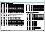
THIRD DIGIT
0
-
1
CH1
2
CH2
3
CH3
THIRD DIGIT
0
-
1
CH1
2
CH2
3
CH3
4
CH4
THIRD DIGIT
See
CH1 Thermocouple Calibration
on Page 21 for a procedure.
See
CH1 RTD Calibration
on Page 22 for a procedure.
DEFAULT 3rd Digit
OBJECT FOR 2nd DIGIT
0
Result
1
Channel 1
2
Channel 2
3
Channel 3
4
Channel 4
5
Channel 5
6
Channel 6
7
Channel 7
THIRD DIGIT
When in this setting, the destination channel
is only updated after the
button is pressed
When in this setting, the destination channel is
updated as the
or
button is pressed
Note*:
For the Manual Loader Mode (Direct Display) to work, with CAL set to [25X] the data source for the
analog output (1 or 2) must be set to [DISP].
Operating range upper and lower limits can be set for the manual loader mode. The setpoint activation
values for setpoint 5 becomes the upper limit and setpoint 6 becomes the lower limit. When either the
direct display or on demand manual loader mode is programmed into the meter, the values for setpoint
5 and setpoint 6 are activated as upper and lower limits.
See Analog Output Supplement (NZ200) for further details.


