


3
2 February, 2005 Code Sheet V4.01d (NZ1001)
Prog.
SP1
SP2
SP4
SP3
SP5
SP6
Prog.
SP1
SP2
SP4
SP3
SP5
SP6
Prog.
SP1
SP2
SP4
SP3
SP5
SP6
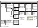
Press
and
hold
Step 1
Step 2
While holding both
buttons, press the Prog.
button.
Step 2
Step 3
Operational Display
Example
Release
after
pressing
Prog.
Press
Code
Blanking
Press and hold
the and
buttons
While holding both
buttons, press the Prog.
button.
Prog.
SP1
SP2
SP4
SP3
SP5
SP6
Release the
the and
buttons and hold
the Prog. button
for approx. 1 sec
then release
Release
after 1
sec
Prog.
SP1
SP2
SP4
SP3
SP5
SP6
Step 4
Press the button to switch
code blanking OFF
Press
1
NOTE: Unless otherwise
requested, the factory
default setting is ON
Code Blanking & Macro
Check Procedure
continued on next column
(Step 6)
Prog.
SP1
SP2
SP4
SP3
SP5
SP6
Press
1
Step 5
Press the Prog. button.
Programming Tip
Code Blanking and Macro ON/OFF
settings revert to the controller’s orig-
inal configuration settings when the
meter is powered off and on.
Prog.
SP1
SP2
SP4
SP3
SP5
SP6
Operational Display
Prog.
SP1
SP2
SP4
SP3
SP5
SP6
Press
1
Step 7
Press the Prog. button.
continued
from Step 5
Prog.
SP1
SP2
SP4
SP3
SP5
SP6
Example
Macro
Prog.
SP1
SP2
SP4
SP3
SP5
SP6
Step 6
Press
1
NOTE: Unless otherwise
requested, the factory
default setting is ON
Press the button to switch
the macro OFF
Code Blanking and Macro Check
Code Blanking
Tiger 380 Series controllers have the ability to hide (blank out) all or some pro-
gramming codes to prevent tampering through the front panel. This function is
known as code blanking and is ideal for preventing settings, such as calibra-
tion, being changed by the operator.
ST
ST
AR
AR
T HERE
T HERE
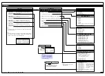
CODE BLANKING & MACRO CHECK PROCEDURE
Macros
A macro is a set of commands that run auto-
matically when the controller is powered up.
Macros can be installed in the controller at the
factory during initial programming or by the cus-
tomer at some later date. Macros are written
and compiled using the Tiger Development
System (TDS) compiler program and loaded
into the controller using either the TDS or the
configuration program.
Prog.
SP1
SP2
SP4
SP3
SP5
SP6
Code
Blanking
Prog.
SP1
SP2
SP4
SP3
SP5
SP6
Press
1
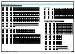
Configuration Utility Program
Code Blanking
ON
(Enabled)
Selected codes hidden (blanked
out) so that the operator cannot
access them thru the front pane
l
Code blanking always reverts
to ON when the meter is
powered up
Prog.
SP1
SP2
SP4
SP3
SP5
SP6
Code
Blanking
Configuration Utility Program
Code Blanking
OFF
(Disabled)
All codes are now visible and
accessible to the operator thru
the front panel
Prog.
SP1
SP2
SP4
SP3
SP5
SP6
Press
1
Code blanking can be set to OFF (disabled) by
the operator by following the Code Blanking and
Macro Check procedure opposite. Setting code
blanking to OFF means that all codes are visible
to the operator and can be tampered with.
To disable (set to OFF) code blanking and/or a macro, carry out the following procedure:
The code blanking function can be either
enabled (set to ON) or disabled (set to OFF)
through the front panel. Changing which
codes are visible, and therefore accessible to
the operator, can only be done through the
Configuration Utility program.
During power-up, the code blanking function
always reverts to ON (enabled). This means that
when the meter is switched ON all codes are vis-
ible except those that have been blanked out
during meter configuration.
Turning the macro OFF means that the controller will not perform the automat-
ic commands pre-programmed to run with the macro. Unless otherwise
requested, Texmate program the controller in the code blanking and macro ON
(enabled) setting. Texmate has a growing library of macros to suit a wide range
of standard customer applications.


