


15
2 February, 2005 Code Sheet V4.01d (NZ1001)
3
38
80
0 S
Se
erriie
es
s
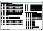
0 Energizes ABOVE setpoint value
HYSTERESIS selected –
relay energizes AT OR ABOVE setpoint value plus
hysteresis counts. De-energizes BELOW setpoint value minus hysteresis
counts.
Note:
If hysteresis set with ZERO counts, relay energizes AT OR ABOVE the setpoint
value.
DEVIATION selected –
relay energizes INSIDE deviation band (setpoint ± devi-
ation counts). De-energizes OUTSIDE deviation band (setpoint ± deviation
counts).
PID selected –
controls ABOVE setpoint value.
1 Energizes BELOW setpoint value
HYSTERESIS selected –
relay energizes BELOW setpoint value minus hys-
teresis counts. De-energizes AT OR ABOVE setpoint value plus hysteresis
counts.
Note:
If hysteresis set with ZERO counts, relay energizes BELOW the setpoint value.
DEVIATION selected –
relay energized OUTSIDE deviation band (setpoint ±
deviation counts). De-energized INSIDE deviation band (setpoint ± deviation
counts).
PID selected –
controls BELOW setpoint value.
2 Energizes AT OR ABOVE setpoint value with FALLING INPUT SIGNAL INITIAL
START-UP INHIBIT
HYSTERESIS selected –
relay energizes AT OR ABOVE setpoint value plus
hysteresis counts with FALLING INPUT SIGNAL INITIAL START-UP INHIBIT.
De-energizes BELOW setpoint value minus hysteresis counts with FALLING
INPUT SIGNAL INITIAL START-UP INHIBIT.
Note:
If hysteresis set with ZERO counts, relay energizes AT OR ABOVE the setpoint
value.
DEVIATION selected –
relay energizes INSIDE deviation band (setpoint ± devi-
ation counts) with FALLING INPUT SIGNAL INITIAL START-UP INHIBIT. De-
energizes OUTSIDE deviation band (setpoint ± deviation counts) with FALLING
INPUT SIGNAL INITIAL START-UP INHIBIT.
PID selected –
controls ABOVE setpoint value.
3 Energizes BELOW setpoint value with RISING INPUT SIGNAL INITIAL START-
UP INHIBIT
HYSTERESIS selected –
relay energizes BELOW setpoint value plus hystere-
sis counts with RISING INPUT SIGNAL INITIAL START-UP INHIBIT. De-ener-
gizes BELOW setpoint value minus hysteresis counts with RISING INPUT SIG-
NAL INITIAL START-UP INHIBIT.
Note:
If hysteresis set with ZERO counts, relay energizes BELOW the setpoint value.
DEVIATION selected –
relay energizes OUTSIDE deviation band (setpoint ±
deviation counts) with RISING INPUT SIGNAL INITIAL START-UP INHIBIT. De-
energizes INSIDE deviation band (setpoint ± deviation counts) with RISING
INPUT SIGNAL INITIAL START-UP INHIBIT.
PID selected –
controls BELOW setpoint value.
Flow
Sensor
Channel 1
Flow Rate
Channel 3
Filled Cases
Totalizer 1
Flow
Channel 2
Bottles
SP5 = 2.00
Hi Setpoint
SP6 = 2.00
Hi Setpoint
SP4 = 12
Hi Setpoint
SP3 = 12
Hi Setpoint
S
O
U
R
C
E
R
E
S
E
T
R
E
S
E
T
I
N
C
R
E
M
E
N
T
I
N
C
R
E
M
E
N
T
S
O
U
R
C
E
S
O
U
R
C
E
S
O
U
R
C
E
Using Setpoints to
Increment and Reset
Registers
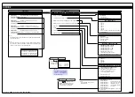
Detailed Descriptions and Explanations
The setpoint reset functions are available on
all 6 setpoints.The various parameters of the
reset function are described as follows.
Trigger Type
The trigger parameter gives the option of
selecting which edge of the relay operation
the reset function, print function, and data
logging function should activate on. It can be
set to either:
•
Off
– Disables all trigger functions
•
Make
– operates on the make edge
only.
•
Break
– operates on the break edge
only.
•
Both
– operates on both make and
break edges.
•
Level
– operates after every sample
period if relay is ON.
Reset Destination
The reset destination parameter defines the
target register in the meter that is to be mod-
ified in some way when the reset trigger con-
ditions for this relay are met. Any Modbus
register number from 111 to 16383 can be
selected as a reset destination. If the [DEST]
parameter is set to [OFF], the reset function
is disabled and the Reset Mode and Reset
Constant/Source selection are not displayed.
The setup sequence jumps straight to the
Print parameter.
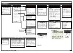
Reset Mode
The reset mode parameter defines what
type of reset effect is required. The following
different options are available.
CONST
– This mode stores a user defined
constant into the selected destination regis-
ter. In most cases this number will be zero
but it can be any number.
I-S+C
– This mode stores the current input
value
I
, defined by the setpoint source,
1st Digit in Setpoint Programming Mode
Following is a detailed description of the options available on the 1st digit of the setpoint
programming mode SPC settings listed on Page 12.
Relay Energize Function
FIRST DIGIT
SETPOINT AND RELAY CONTROL FUNCTION SETTINGS
minus the setpoint value
S
plus a user
defined constant
C
. It would normally be
used with a counting or totalizing application
where the amount of setpoint overshoot
needs to be retained after the reset function.
The constant value would normally be zero
but could be used to provide an offset if
required.
D+C
– This mode adds the user defined con-
stant
C
to the current value in the selected
reset destination register
D
. It can be used to
increment or decrement a register by any
amount.
REG
– This mode copies the contents of a
user selectable register into the reset desti-
nation register (see Reset Constant to select
the source register).
It can be used to capture data on an event
and store it in an unused channel for display
or analog output, etc.
Reset Constant
This parameter defines the constant value to
be used in the
CONST
,
I-S+C
,
D+C
modes
as previously explained. Its default value is
zero. This parameter is not available if
REG
is selected as the reset mode.
Source (only available in Reg mode)
If the reset mode is set to
REG
then the
source parameter allows you to select the
number of the Modbus register in the meter
to be copied to the reset destination register.
Resetting and Incrementing Using
Setpoints
Setpoints may be used to reset and/or incre-
ment registers. In the example shown oppo-
site, 2 liter soft drink bottles are being filled
and packed 12 to a case. Using the setpoint
reset and increment feature, the number of
bottles and the total number of filled cases is
easily calculated and displayed. Totalizer 1
counts from 0 to 2, resets, and repeats. CH2
counts from 0 to 12, resets, and repeats.
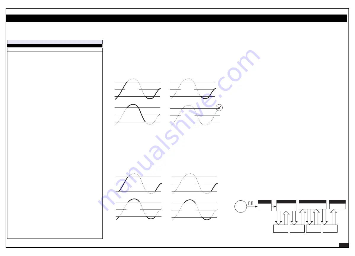
Each setpoint can be individually programmed to energize the relay in the hysteresis or devi-
ation mode, with or without initial start-up inhibit.
Hysteresis
(also known as deadband) is the programmable band above and below the set-
point value that determines when and for how long the relay is energized or de-energized. The
setpoint can be programmed to energize the relay above or below the setpoint value.
The hysteresis setting can be any value between 0 and 65535 counts. The number of counts
selected act both positively and negatively on the setpoint, forming a hysteresis band around
the setpoint. For example, if the setpoint setting is 500 counts and the hysteresis setting is 10
counts, the hysteresis band around the setpoint setting is 20 counts, starting at 490 counts and
ending at 510 counts.
SP
Hysteresis
Band
SP
Hysteresis
Band
Energized Below
Energized Above
Hytseresis
+
–
+
–
SP
Hysteresis
Band
Energized Below
Hytseresis with Initial Start Up Inhibit
+
–
SP
Hysteresis
Band
Energized Above
+
–
ONLY when 2nd phase of signal rises
above hysteresis band
SP
Deviation
Band
SP
Deviation
Band
Energized Inside
Energized Outside
Deviation
+
–
+
–
SP
Deviation
Band
Energized Inside
Deviation with Initial Start Up Inhibit
+
–
SP
Deviation
Band
Energized Outside
+
–
Explanation of Hysteresis and Deviation Functions
Deviation
(passband) is the programmable setting around which the setpoint can be pro-
grammed to energize the relay inside or outside the deviation band. The deviation setting can
be any value between 1 and 65535 counts. The number of counts selected act both positive-
ly and negatively on the setpoint, forming a deviation band around the setpoint.
For example, if the setpoint setting is 1000 counts and the deviation setting is 35 counts, the
deviation band around the setpoint setting is 70 counts starting at 965 counts and ending at
1035 counts.
See Setpoints & Relays Supplement (NZ201) for a detailed explanation of the hysteresis and
deviation modes.
Explanation Of Setpoint Trigger Functions


