5
2 February, 2005 Code Sheet V4.01d (NZ1001)
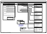
CALIBRATION MODE
CALIBRATION MODES FOR INPUT AND OUTPUT
0 No function
1 On Demand TARE from the PROGRAM button
2 On Demand Single-point Calibration from the PRO-
GRAM button (requires single input source)
3 On Demand 2-point Calibration from the PROGRAM
button (requires dual input source)
4 On Demand Primary Input Compensation Mode from
the PROGRAM button
5 On Demand Manual Loader Mode (no increase /
decrease with HOLD active)
6 -
7 -
Note:
When in the TARE mode, a decimal point appears at the right
of the display indicating that the tare value is NOT zero.
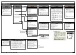
FIRST DIGIT
SECOND DIGIT
0 Manual Calibration
(requires NO input source)
1 2-point Calibration (requires dual input source)
2 Calibrate Thermocouple (requires K type thermocouple
input source)
3 Calibrate RTD (requires RTD 385 input source)
4
Note: For future development
5 Calibrate Analog Output mA/V (Single analog out requires
multimeter connected to pins 2 and 3 on Terminal 4)
6 -
7 -
0 Serial Communications Properties
1 Set Auto Zero Maintenance for 3rd digit
2 Set Averaging Samples & Averaging Window for 3rd digit
3 Totalizer Settings Mode
4 Setup 32-point Linearization Tables
5 Scale Analog Output LOW/HIGH Scale Range Settings
6 -
7 -
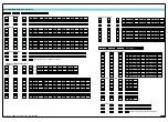
OBJECT FOR 2nd DIGIT
0
Result
1
Channel 1
2
Channel 2
3
Channel 3
4
Channel 4
5
Channel 5
6
Channel 6
7
Channel 7
THIRD DIGIT
This is the default 3rd digit box. If not point-
ing to another 3rd digit box, all 2nd digit
settings should be regarded as pointing to
here. It is identified on Pages 6 and 7 by
the following box:
0
-
1
CH1
2
CH2
3
CH3
0
-
1
CH1
2
CH2
3
CH3
4
CH4
5
CH5
6
CH6
7
CH7
0
-
1
CH1
2
CH2
3
CH3
4
CH4
5
CH5
6
CH6
7
CH7
0
-
1
Total 1
2
Total 2
3
Total 3
4
Total 4
5
Total 5
6
Total 6
0
-
1
Port 1
2
Port 2
3
Port 3
Converting °F to °C
See User Notes on Page 21 for a procedure.
See
CH1 Thermocouple
Calibration
on Page 21
for a procedure.
See
CH1 RTD
Calibration
on Page 22
for a procedure.
CHANNELS 5, 6, 7
Not available thru front panel controls.
Can only be setup via serial port using
Texmate’s Meter Configuration Utility
program, or accessed via a macro.
See Page 6 for a
breakdown of the
sub-menu
See Page 6 for a
breakdown of the
sub-menu
See Page 7 for a
breakdown of the
sub-menu
2
1
3
+
Single
Analog
Output
(AIC or
AIV)
Analog Output TERMINAL 4
2
1
3
+
+
Dual
Analog
Output
(ADV)
0 Functions Activated
by Pressing the
PROGRAM Button
1 Calibration
Procedures
2 Related Calibration
Functions
3 -
Using the Calibration Mode
1) Press the
and
buttons at the same time.
The controller enters the brightness menu [BRI].
Press the
button again to enter the Calibration
Mode.
2) With [CAL] [XXX] toggling on the display, set the
1st, 2nd, and 3rd digits to their required settings.
3) Press the
button to enter the selected sub-
menu and select the required calibration settings
from the sub-menus displayed.
4) Press the
button repeatedly to return to the
operational display (bypassing Codes 1 to 9).
Note:
Once the 3-digit settings have been entered for
an on-demand function [CAL] [0XX], pressing
the
button saves the selected on-demand
setting and moves to Code 1.
When in the operational display, press the
button for 4 seconds to activate the selected
on-demand function and display the relevant
sub-menu settings (except [01X] which has no
sub-menu).
DEFAULT 3rd Digit
0
-
1
Analog Output 1
2
Analog Output 2
3
Analog Output 3
4
Analog Output 4
5
Analog Output 5
6
Analog Output 6
7
Analog Output 7
Note: Settings 3-7
not available at
present
0
-
1
Analog Output 1
2
Analog Output 2
3
Analog Output 3
4
Analog Output 4
5
Analog Output 5
6
Analog Output 6
7
Analog Output 7
Note: Settings 3-7
not available at
present
Note: Port 3 only
available on certain
input modules


