Texmate Tiger 380 Series Programming Manual Download Page 11

11

2 February, 2005   Code Sheet V4.01d (NZ1001)

CODES 6 to 9

CH4 POST PROCESSING

0 Direct Display of Input (no pro-

cessing)

1 Square Root of Channel 4
2 Inverse of Channel 4
3 32-point Linearization of CH4 using

Table 4

Note:

All linearization tables are set up
in the Calibration Mode [24X].

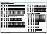
CODE 6 – CHANNEL 4 FUNCTIONS

FIRST DIGIT

SECOND DIGIT

THIRD DIGIT

FOR THERMOCOUPLE

0 Type J
1 Type K
2 Type R
3 Type S
4 Type T
5 Type B
6 Type N
7 For sensor tables other than those

listed above contact Texmate

FOR RTD TYPE  (2-, 3-, 4- WIRE)

0 Resistance

1 Pt 385 100 

RTD

2 Pt 392 100 

RTD

3 Ni 120 

RTD

4 Cu 10 

RTD

MEASUREMENT TASK

0 No Function

1 Voltage, Current

2 TC

(3rd digit selects type of TC).

3 RTD/Resistance

(3rd digit selects type of RTD).

4 Real Time Clock and Timer

(3rd digit selects type)

5 -

6 -

7 Smart Input Module

(3rd digit selects register)

FOR SMART INPUT MODULE

0 Output Register 1
1 Output Register 2
2 Output Register 3
3 Output Register 4
4 Output Register 5
5 Output Register 6
6 Output Register 7
7 Smart Input Module 

Register 3

Code Setup

RESULT PROCESSING

0 Direct Display of Result

as per processing per-
formed in 2nd and 3rd
digits

1 Square Root of Result
2 Inverse of Result
3 -

32-POINT LINEARIZATION FOR RESULT

0  No Linearization on Result

1  32-point Linearization on Result using Table 1
2  32-point Linearization on Result using Table 2.
3  32-point Linearization on Result using Table 3.
4  32-point Linearization on Result using Table 4.
5  125-point Linearization on Result (Tables 1 to 4 cascaded)
6 32-point Linearization on Result (Tables 1 to 4 selected

from the rear of the meter).
The selected table is not available if CH2, CH3, or CH4 is
operating in the analog mode. CH1 must be set to Voltage,
Current in Code 2 [X0X].

7 –

MATHS FUNCTIONS FOR RESULT

0  Result Register not Updated

1  pH Meter (CH1 = Tbuff, CH2 = pH)
2  Result = CH1, Setpoint 2 = CH2
3  Result = CH1 + CH2
4  Result = CH1 - CH2
5  Result = CH1 x CH2/10 000
6  Result = (CH1 x 20 000)/CH2
7 Result = Parameter at result

source register (#4450)

See Note 8

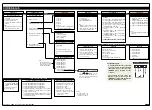
CODE 7 – RESULT PROCESSING

CODE 8 – DATA LOGGING AND PRINT MODE OPTIONS

FIRST DIGIT

SECOND DIGIT

THIRD DIGIT

DATA LOG BUFFER TYPE

0 No Data Logging

1 Cyclic 

Buffer

2  Linear FIFO Buffer.
3  Reset Buffer Number to 0.

Note:

Setting Code 8 to [3XX] resets the
data log buffer to 0. Once reset,
Code 8 must be set back to the
required data log buffer setting.

DATE & TIME STAMP OPTIONS

0 Printer Format – No time stamp with

print/log

1 Printer Format – Time stamp format 1 [Mth-

Day-Yr  Hrs:Min:Sec] (with <CR><LF>)

2 Printer Format – Time stamp format 2 [Day-

Mth-Yr  Hrs:Min:Sec] (with <CR><LF>)

3 Printer Format – Time stamp format 3

[Hrs:Min:Sec] (with <CR><LF>)

4 Spreadsheet Format – No time stamp with

print/log

5 Spreadsheet Format – Time stamp format 1

[Mth-Day-Yr  Hrs:Min:Sec]

6 Spreadsheet Format – Time stamp format 2

[Day-Mth-Yr  Hrs:Min:Sec]

7 Spreadsheet Format – Time stamp format 3

[Hrs:Min:Sec]

ALL ABOVE ARE REAL-TIME CLOCK OPTIONS

LOG OR PRINT TRIGGER

0 No 

trigger

1  Trigger on Demand from PRO-

GRAM Button

2  Trigger on Demand from F1 Button
3  Trigger on Demand from F2 Button
4  Trigger on Demand from HOLD Pin
5  Trigger on Demand from LOCK Pin
6 -
7 -

Note:

Log and/or Print will only trigger if
enabled.

DISPLAY TEST PIN

0 Display test only

1  Reset Counter Channel 1, total  2,

and auto zero at Power-up

2  Reset Counters Channel 1, 2, Total

1, and Total 2 at Power-up

3  Reset Total 1, and Total 2, and auto

zero at Power -up

HOLD PIN

0 Display 

Hold

1  Reset Channel 1
2  Reset  Total 1 and Total 2
3 Reset 

Total 

2

4  Reset Peak 1, Valley 1
5 Clear 

Tare

6 Set Tare
7 Unlatch (de-energize) all Setpoints

LOCK PIN

0 Key 

Lock

1  Reset Channel 1
2  Reset Channel 2
3  Reset Channel 3
4  Reset Channel 4
5 Clear 

Tare

6 Reset Total 1
7 Unlatch (de-energize) all Setpoints

CODE 9 – FUNCTIONS FOR DIGITAL INPUT PINS

FOR REAL-TIME CLOCK & TIMER

0 HRS:MIN:SEC

1 HRS:MIN
2 -
3 -
4 1 Second Count UP Timer
5 1 Second Count DOWN Timer
6 -
7 -

Note:

The function of the out-
put register selected
varies according to the
input module installed.

Use the 

buttons to set the

required smart input module code (0 to
377). See specific input module data
sheet for code details.

Note 7:

Register 4450 can
only be setup via the
serial port or a macro.
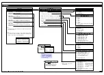
2

1

3

4

5

LOCK

HOLD

TEST

COMMON

CAPTURE

TERMINAL 2 – Function Pins

Programming Tip

For digital input functions selected in
Code 9 to operate, the relevant digital
input pin must be connected to the
COMMON pin on Terminal 2 of the
controller.

The example opposite shows the
HOLD pin (pin 1) connected to the
COMMON pin (pin 4) with the selected
function activated by a switch.

Summary of Contents for Tiger 380 Series

Page 1: ...isplay text editing Configuration data copying Downloading macros to the meter Tamper proof settings Tiger 380 Series controllers except the DI 802 have tamper proof lockout switches to prevent users...

Page 2: ...e holding both buttons press the Prog button then release all three buttons Press and hold the and buttons Programming Tip The Model and Software Code Version check ing procedure can be performed at a...

Page 3: ...n the controller is powered up Macros can be installed in the controller at the factory during initial programming or by the cus tomer at some later date Macros are written and compiled using the Tige...

Page 4: ...put pins on the rear of the con troller Display test pin Hold pin Lock pin The Setpoint and Relay Control Settings diagram on Pages 12 to 14 shows the three digit configuration settings that are appli...

Page 5: ...Port 2 3 Port 3 Converting F to C See User Notes on Page 21 for a procedure See CH1 Thermocouple Calibration on Page 21 for a procedure See CH1 RTD Calibration on Page 22 for a procedure CHANNELS 5 6...

Page 6: ...t input module data sheet for setup procedures Use buttons to set CAL_LO Use buttons to set CAL_HI 0 Manual Calibration requires NO input source 1 2 point Calibration requires dual input source 2 Cali...

Page 7: ...signal channel must be selected in the 3rd digit when configuring a lin earization table using the auto setup mode 0 1 CH1 2 CH2 3 CH3 4 CH4 5 CH5 6 CH6 7 CH7 THIRD DIGIT THIRD DIGIT THIRD DIGIT Use...

Page 8: ...NDARY display is the bargraph display Note 3 These functions are only available on selected input modules Note 4 If Code 1 s display modes have been entered second digit set to 5 6 or 7 the display wi...

Page 9: ...r 2 2 Output Register 3 3 Output Register 4 4 Output Register 5 5 Output Register 6 6 Output Register 7 7 Smart Input Module Register 1 Code Setup See Note 6 THIRD DIGIT FIRST DIGIT SECOND DIGIT CODE...

Page 10: ...1 Frequency 999 99 Hz range from 0 01 Hz 2 Frequency 99 999 kHz range from 1 Hz 1 s gate 3 Frequency 500 kHz range from 10 Hz 0 1 s gate 4 Pulse 50 0000 s 100 s resolution 5 Period 999 99 ms 10 s reso...

Page 11: ...ear FIFO Buffer 3 Reset Buffer Number to 0 Note Setting Code 8 to 3XX resets the data log buffer to 0 Once reset Code 8 must be set back to the required data log buffer setting DATE TIME STAMP OPTIONS...

Page 12: ...Relay Reset 4 Relay Latched Off 5 Mode Hysteresis Deviation PID SP Flashing SP Tracking 6 Timer Modes OFF Normal Delay Repeat ON Pulse ON 1 Shot ON Repeat OFF Pulse OFF 1 Shot OFF Note In PID Mode al...

Page 13: ...o 6553 5 65 535 secs On_t 0 1 0 001 to 6553 5 65 535 secs Off time oFF_t 0 1 0 001 to 6553 5 65 535 secs Off time oFF_t 0 1 0 001 to 6553 5 65 535 secs Minimum off time M_of 0 1 to 6553 5 secs Set Up...

Page 14: ...ct reset trigger from 1 of 4 relay operating edges Reset Trigger Select register to be reset Reset Destination Register Select Reg in reset mode Reset Mode Copy contents of selected register SP1 to SP...

Page 15: ...ble CONST This mode stores a user defined constant into the selected destination regis ter In most cases this number will be zero but it can be any number I S C This mode stores the current input valu...

Page 16: ...nual Calibration 2 point Calibration INPUT INPUT 111 ZERO SPAN INPUT INPUT 112 ZERO SPAN INPUT INPUT 113 ZERO SPAN INPUT INPUT 114 ZERO SPAN INPUT INPUT 025 SPAN 035 ZERO SPAN 045 CHANNEL 055 CHANNEL...

Page 17: ...Analog Output 152 CAL LOW CAL HIGH OUTPUT OUTPUT SOURCE SOURCE 1st DIGIT 2nd DIGIT 3rd DIGIT SUB SETTINGS TC TYPE UNITS TC TYPE UNITS TC TYPE UNITS 121 ZERO SPAN INPUT INPUT Calibrate RTD 122 ZERO SPA...

Page 18: ...IGIT CODE 4 PRESCALER 1st DIGIT 2nd DIGIT 3rd DIGIT CODE 5 SMART INPUT MODULE SETTINGS 1st DIGIT 2nd DIGIT 3rd DIGIT CODE 6 SMART INPUT MODULE SETTINGS 1st DIGIT 2nd DIGIT 3rd DIGIT CODE 7 1st DIGIT 2...

Page 19: ...ING SPAN PB INT DER ARW MCT SP TRACKING SPAN PB INT DER ARW MCT SP TRACKING TIMER MODE SETTINGS SPC_1 _ _ 6 SPC_2 SPC_3 SPC_4 SPC_5 SPC_6 _ _ 6 _ _ 6 _ _ 6 _ _ 6 _ _ 6 SPC SETTING NORMALLY OFF PULSED...

Page 20: ...setpoint with the contents of a selected source register Setpoint Control Settings XX7 Select the contents of one register to be copied into another register by a setpoint The 38 named registers that...

Page 21: ...he Calibration mode CAL set to 111 and fine tune the thermocouple calibration over the required temperature range Fine Tune Calibration over Specific Temperature Range Follow Steps 1 to 5 for setting...

Page 22: ...ls 2 and 3 using the following settings CH2 Code 4 210 for type 385 CAL 132 to calibrate type 385 Code 4 2X0 to select specific RTD CAL 112 to fine tune selected RTD CH3 Code 5 X31 for type 385 CAL 13...

Reviews: