


CHAPTER 4 |
49
APPENDIX
Finally, return to the VX Studio page and configure the GPIO Actions and Indications as outlined in the Individual Studio
Configuration section of this manual.
Notes on LW Channel number assignment:
In this example, the IP address of the VX Engine is 192.168.2.158 and the xNode is 192.168.2.215. We have taken the last byte
of the IP addresses and made it the first three digits in the channel numbers used. This does two things for us: 1) It reduces
the chances of accidentally creating duplicate LW channels. 2) It’s easy for us to see which device is which when the channel
number references the IP address like this. Looking at the VX’s Studio configuration page, we can gather the IP address info for
both devices involved. Pretty cool.
Physical GPIO Reference
The GPIO (General Purpose I/O) feature set in the VX Enterprise and VX Prime+ is the most advanced feature set we’ve ever
implemented. It’s totally customizable and you only need to use the features you need. That means no more wasted pins on the
physical GPIO port.
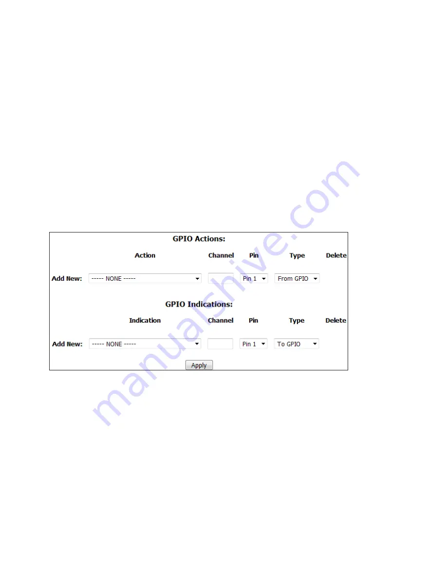
Each Studio has two sections for GPIO. GPIO Actions are inputs to the system to remotely engage a feature or option, while
GPIO Indications are outputs to drive indicators, as the name suggests. We’ve described these fields in the section covering
Studio Profiles, but we’ll repeat them here in slightly more detail. If there are currently no GPIO settings configured, you’ll
only have the
Add New
fields showing. The
Action
or
Indication
drop-down menus allow you to choose what function this
particular GPIO pin will assume. The choices are:
Actions:
Take next call, Take next ringing line, Hold all calls, Drop all calls, Enable Block All, Disable Block All, Toggle Block
All, Toggle Auto Answer & Auto Hold, Mute Ringer, Change Shows.
Indications:
Next call available, Line Ringing, Line Ringing (Busy All), Line ringing (non-Busy All), Call can be held, Call can
be dropped, Block All enabled, Auto Answer and Hold enabled, Ringer muted, Delay Dump, Current show.
Channel
is where a unique Livewire channel number will go. This will be referenced later in the xNode configuration.
Select which
Pin
the GPIO will happen on. There are 5 input and 5 output pins per GPIO port.
For
Type
, we are specifying if this is an input (from GPIO) or an output (To GPIO). The default settings are sufficient here.


