


xE922-3GR Hardware User Guide
1VV0301272
Rev.0.8 2017-01-05
Reproduction forbidden without written authorization from Telit Communications S.p.A. - All Rights
Reserved.
Page 92 of 112
remove or install the xE922-3GR module. Antennas used for this OEM module must not exceed
3dBi gain for mobile and fixed operating configurations.
16.1.1.
GSM/WCDMA Antenna
–
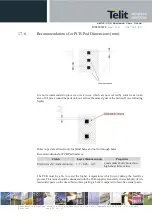
PCB line Guidelines
·
Make sure that the transmission line’s characteristic impedance is 50ohm.
·
Keep the line on the PCB as short as possible since the antenna line loss should be less than
around 0.3dB.
·
Line geometry should have uniform characteristics, constant cross section, avoid meanders
and abrupt curves.
·
Any suitable geometry/structure can be used for implementing the printed transmission line
affecting the antenna.
·
If a Ground plane is required in the line geometry, that plane must be continuous and
sufficiently extended so the geometry can be as similar as possible to the related canonical
model.
·
Keep, if possible, at least one layer of the PCB used only for the Ground plane; if possible,
use this layer as reference Ground plane for the transmission line.
·
It is wise to surround (on both sides) the PCB transmission line with Ground. Avoid having
other signal traces facing directly the antenna line trace.
·
Avoid crossing any un-shielded transmission line footprint with other traces on different
layers.
·
The Ground surrounding the antenna line on the PCB must be strictly connected to the
main Ground plane by means of via-holes (once per 2mm at least) placed close to the
ground edges facing the line trace.
·
Place EM-noisy devices as far as possible from xE922-3GR antenna line.
·
Keep the antenna line far away from the xE922-3GR power supply lines.
·
If EM-noisy devices are present on the PCB hosting the xE922-3GR, such as fast switching
ICs, take care to shield them with a metal frame cover.
·
If EM-noisy devices are not present around the line, using geometries such as Micro strip
or Grounded Coplanar Waveguide is preferred since they typically ensure less attenuation
compared to a Strip line having the same length.
16.1.2.
GSM/WCDMA Antenna
–
Installation Guidelines
·
Install the antenna in a location with access to the network radio signal.
·
If the chosen antenna is a style which requires a ground plane, ensure that it is
properly attached, both electrically and mechanically, to a ground plane with
dimensions and mechanical structure as recommended by the antenna manufacturer
·
The antenna must be installed such that it provides a separation distance of at least 20
cm from all persons and must not be co-located or operating in conjunction with any
other antenna or transmitter;
·
The antenna must not be installed inside metal cases;