


xE922-3GR Hardware User Guide
1VV0301272
Rev.0.8 2017-01-05
Reproduction forbidden without written authorization from Telit Communications S.p.A. - All Rights
Reserved.
Page 71 of 112
12.
Peripheral interfaces
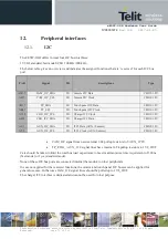
12.1.
I2C
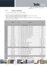
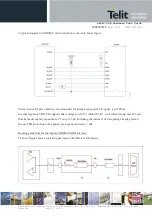
The xE922-3GR offers in total four I2C bus interfaces.
1V8 IO, standard/fast mode SCLK 100 kHz/400 kHz.
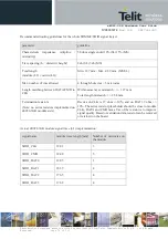
The below table gives an overview and indicates the assigned functions that are
‘
reserved
’
for each I2C bus
port.
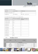
PAD
Signal
I/O
descriptions
Type
AM17
CAM_I2C_SDA
I/O
Camera I2C Data
CMOS 1.8V
AP17
CAM_I2C_SCL
I/O
Camera I2C Clock
CMOS 1.8V
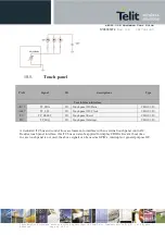
AD17
TP_SDA
I/O
Touch panel I2C Data
CMOS 1.8V
AB17
TP_SCL
I/O
Touch panel I2C Clock
CMOS 1.8V
AC18
CHG_I2C_SCL
I/O
Charger I2C Clock
CMOS 1.8V
AE18
CHG_I2C_SDA
I/O
Charger I2C Data
CMOS 1.8V
AS1
AUX_I2C_SDA
I/O
I2C3 Data (AUX / Sensors)
CMOS 1.8V
AT2
AUX_I2C_SCL
I/O
I2C3 Clock (AUX / Sensors)
CMOS 1.8V
·
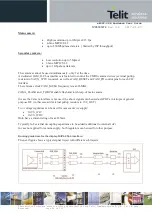
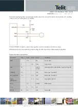
CAM_I2C signal lines need external 2.2k pullup resistors to VAUX_1P8V.
·
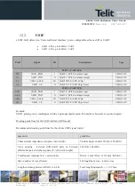
TP_/CHG_/AUX_ I2C signal lines have internal 2.2k pullup resistors to 1V8_OUT
Care should be taken to limit the total bus load capacitance to meet maximum rise time requirement of 300ns
(fast-mode) or 1 µs (standard-mode).
None of these I2C bus ports are connected internal the module to other peripherals.
In case not applied for the reserved functions, the camera and touch panel I2C busses can be applied for
general use case. In that case CAM_I2C signal lines should be pulled up to 1V8_OUT.
The charger I2C interface is dedicated and cannot be used for other purpose