


xE922-3GR Hardware User Guide
1VV0301272
Rev.0.8 2017-01-05
Reproduction forbidden without written authorization from Telit Communications S.p.A. - All Rights
Reserved.
Page 52 of 112
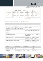
Minimize parasitic resistance in the current path by using thick copper traces between sense resistor and PCB
ground and negative battery terminal respectively.
The fuel gauge FG_IBATP/N signal pair should be routed as differential and isolated from aggressors (like
clocks, DC/DC switching nodes) to minimize noise interference.
A low pass filter 4.7k/1uF is present inside the xE922-3GR module.
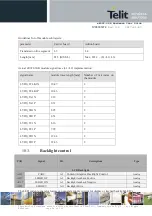
When using 2-teminal resistor, apply 4-wire terminal layout pattern scheme as suggested in following figure.
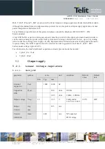
7.2.
Battery charging
The system SW supports application of an external charger IC solution BQ24296 from Texas Instruments TI,
an I2C controlled, 3A single cell, USB Charger. For detailed performance, please consult the datasheet.
Please consult
Intel’s IBL
support website for application note and actual supported charger IC type numbers.
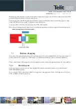
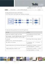
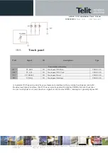
7.2.1.
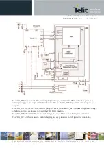
Block diagram
The below figure gives an overview how the BQ24296 solution should be interfaced with the onboard
PMU/ABB/DBB functions.
Note: currently PSEL control from ABB is not supported. Charging from USB or DC-adapter is set by tying
PSEL to HIGH or LOW respectively.