


xE922-3GR Hardware User Guide
1VV0301272
Rev.0.8 2017-01-05
Reproduction forbidden without written authorization from Telit Communications S.p.A. - All Rights
Reserved.
Page 90 of 112
15.2.
Digital
15.2.1.
I2S
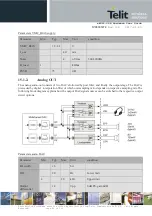
As mentioned in the USIF part, USIF1 interface pins , on top of SPI or UART, can be configured as audio I2S
port as well .The below table shows the multiplex pinout in case configured for I2S interface:
USIF1-I2S pin mapping
W5
USIF1_RXD
I
I2S1_RX
CMOS 1.8V
Y5
USIF1_TXD
O
I2S1_TX
CMOS 1.8V
S5
USIF1_SCLK
I/O
I2S1_CLK0
CMOS 1.8V
U5
USIF1_CS
O
I2S1_WA0
CMOS 1.8V
15.2.2.
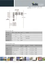
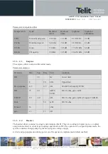
Digital microphone
Digital microphone
AV12
DIG_MIC_CLK
DI
Digital microphone Clock Output
CMOS 1.8V
AN12
DIG_MIC_D1
DI
Digital microphone 1 signal input;
CMOS 1.8V
AT12
DIG_MIC_D2
DI
Digital microphone 2 Clock input;
CMOS 1.8V
AG18
MIC_VDD
AO
MEMC/DIG Microphone Power Supply
power
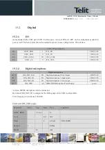
A stereo MEMS microphone can be connected.
By default DIG_MIC_D1 is sampled at the falling edge of the CLK (configurable).
CLK frequency is minimum 1.96 MHz
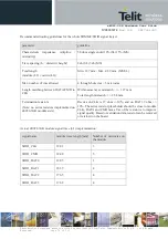
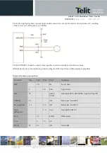
Parameters MIC_VDD supply:
Parameter
Min
Typ
Max
Unit
condition
VMIC_BIAS
1.9..2.2
V
I_out
4.0
mA
Noise
4
µVrms
300-3900Hz
R_load
1
kOhm
PSSR
75
dB