EQUIPMENT SET-UP
UNPACKING
Unpack your BTR-200 and TR-200 System. If
there are any damages or shortages, refer to the
“Warranty Service Information" section in this
manual.
ANTENNA INFORMATION
ANTENNA CONNECTIONS
The BTR-200 is supplied with two (2) anten-
nas. One 5/8-wave antenna for Transmit and
one 5/8-wave for Receive.
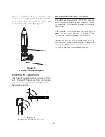
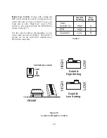
Assemble the 5/8-wave antenna by screwing
the three sections
into one another as shown in
Figure 8. All three sections of the BTR-200
5/8-wave a
ntennas must be used. Leaving out a
section will result in reduced distance capabil-
ity.
Figure 8
5/8-wave Antenna Assembly
To insure that the frequency range of the anten-
nas match the receiver and transmitter of the
BTR-200, match the color code on the antenna
with the color code on the BTR-200.
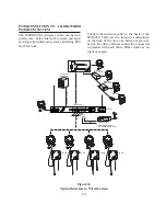
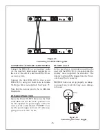
Attach the receive 5/8-wave antenna to the an-
tenna input receptacle labeled “Receive An-
tenna” on the right side of the rear panel via
the supplied connectors. Attaching the angled
connector to the base station receptacle first,
then attaching the straight connector, as shown
in Figure 9, will prevent antenna sway.
Figure 9
Attaching 5/8-wave Antenna
-13-
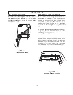
DO
DON’T

