background image

Figure 6

External Controls, TR-200

-11-

bat/

ovmod

talk

talk

BELT CLIP

LOW BATTERY / OVERMODULATION

INDICATOR LED

TALK LED INDICATOR

PUSH-TO-TALK/

LOCK-TO-TALK SWITCH

VOLUME OFF/ON CONTROL

HEADSET JACK

TRANSMIT ANTENNA

RECEIVE ANTENNA

R

Summary of Contents for BTR-200B II

Page 1: ...INTERCOM SYSTEM TR 200 TR 200P BTR 200 II BTR 200B II 1 RadioCom R T E L E X Ext Intercom Aux Audio 1 3 4 2 Portable Stations Carrier Status BTR 200 II Mic On Push Twice to Latch Headset Controls Volu...

Page 2: ...EQUIPMENT SET UP 13 UNPACKING 13 ANTENNA INFORMATION 13 ANTENNA CONNECTIONS 13 ANTENNA POLARIZATION 14 DISTANCE BETWEEN ANTENNAS 14 ANTENNA PLACEMENT 15 IMPROVING RECEPTION INCREASING RANGE 16 BTR 200...

Page 3: ...TALK PUSH TO TRANSMIT SWITCH 28 BATTERY REMOVAL 29 ENABLING AUDIO 30 PORTABLES 30 WIRED INTERCOM 30 AUXILIARY 30 SETTING SYSTEM GAIN LEVELS 31 ADJUSTING GAIN 31 BTR 200 BASE STATION 31 TR 200 PORTABL...

Page 4: ...the remotes may communicate with each other with a wired intercom system or with an auxil iary system The BTR 200 Base Station with its one transmit and four receive channels was designed to operate i...

Page 5: ...con tinuous transmit mode with the audio to talk activated by a switch As many as four TR 200 belt pack transceivers can operate in a fully duplex network with one Telex Model BTR 200 or BTR 200 II B...

Page 6: ...2 mV RMS input nominal 1 5 mV RMS input at compression Dynamic Local Headset Output 32 mV maximum output into 600 ohmst Temperature Range 4 F to 130 F 20 C to 55 C Dimensions 15 75 W x 1 75 H x 10 5...

Page 7: ...mA source Intercom connections with the ability to in terface with most wired intercom systems RF LED indicator for each portable station All metal case for superior shielding Molded front panel for a...

Page 8: ...adset microphone audio function NOTE DOES NOT control base station RF transmit Local Push to Talk Indicator Will be illumi nated whenever the talk function is on Local Microphone Gain Control and Over...

Page 9: ...tioning solely as a monitor In the CONT po sition the transmitter is always on This continuous mode is recommended over the REMOTE mode In the REMOTE posi tion the transmitter is enabled only when on...

Page 10: ...n Push Twice to Latch Headset Controls Volume Power Headset INTERCOM INDICATOR AUXILIARY LEVEL CONTROL PORTABLE CARRIER INDICATORS Ext Intercom Aux Audio 1 3 4 2 Portable Stations Carrier Status Porta...

Page 11: ...IONS INC FCC I D B5DBTR 200 MADE IN U S A Jack Gain AC DC 13 O V 300 mA Transmit AUXILIARY OUTPUT CONNECTOR AUXILIARY INPUT CONNECTOR INTERCOM CONNECTORS Receive Antenna Intercom Loop Thru RECEIVE ANT...

Page 12: ...onds Pre emphasis Modulation Limiter Internal Compressor Modulation Frequency Range 300 to 5000 Hz _ 2 dB Microphone Audio Input 30 to 3500 ohms Microphone Input Sensitivity 2 mV Dynamic 4 mV Electret...

Page 13: ...l Overmodulation Indicator Uses the same LED as the low battery indicator During the talk mode if the microphone gain is too high the LED will illuminate when talking Push To Talk Lock To Talk Switch...

Page 14: ...al Controls TR 200 11 bat ovmod talk talk BELT CLIP LOW BATTERY OVERMODULATION INDICATOR LED TALK LED INDICATOR PUSH TO TALK LOCK TO TALK SWITCH VOLUME OFF ON CONTROL HEADSET JACK TRANSMIT ANTENNA REC...

Page 15: ...lt clip and prying out the small rubber plug to the right of the screw boss Dynamic Electret Switch This switch allows selection of D when using a Dynamic Micro phone or E when using an Electret Micro...

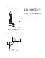
Page 16: ...e antennas must be used Leaving out a section will result in reduced distance capabil ity Figure 8 5 8 wave Antenna Assembly To insure that the frequency range of the anten nas match the receiver and...

Page 17: ...N ANTENNAS The distance between the BTR 200 Receive and Transmit antennas is not adjustable when the antennas are connected directly on the back of the unit The antennas can be remoted for better sign...

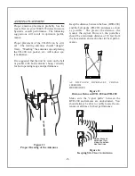
Page 18: ...gnal However the portables should be a minimum distance of 10 feet from the base station and each other for best perfor mance AS DISTANCE INCREASES SIGNAL STRENGTH DECREASES Figure 13 Distance Between...

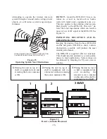
Page 19: ...ortable Stations Carrier Status BTR 200 II Mic On Push Twice to Latch Headset Controls Volume Power Portable Station Connect T E L E X SIGNAL REFLECTION OFF A METAL OBSTRUCTION CAUSES REDUCED SIGNAL A...

Page 20: ...r on the BTR 200 Remove three 6 32 x 3 8 screws on both sides of the unit Remove four 4 40 x 3 16 screws on the top front and loosen three 4 40 x 3 16 screws on the back of the unit The cover will sli...

Page 21: ...BTR 200 as shown in Figure 18 For the correct setting corresponding to your wired intercom unit see Table 2 The switch is factory set for use with Telex AudioCom or RTS wired intercoms Table 2 Figure...

Page 22: ...nt brackets supplied on ei ther side of the unit and insert three 6 32 x 3 8 screws for each bracket Tighten the screws securely Insert the BTR 200 into your 19 rack enclo sure and insert four 4 10 32...

Page 23: ...hone stand bracket not supplied See Accessory section for order information You will also need to remote the transmit an tenna in the same manner Connect a coax ca ble assembly to the transmit antenna...

Page 24: ...WITH THE DY NAMIC ELECTRET SWITCH LOCATED ON THE REAR OF THE UNIT TRANSMIT SWITCH Allows the operator to select three different types of transmitting modes continuous trans mitter transmitter off or...

Page 25: ...ther a female connector connected in parallel with each other Either works as an input or output Figure 24 Typical Interface to Wired System 22 T E L E X T E L E X T E L E X T E L E X EXTERNAL SPEAKER...

Page 26: ...the front of the BTR 200 is in the OFF position Con nect the supplied AC power supply cord to the receiver at the socket labeled POWER Con nect the power supply unit to an AC outlet sup plying 105 to...

Page 27: ...Electret This switch is accessible by removing the belt clip and re moving the battery holder A 5 volt bias is available at the microphone plug for electret use If you are using a headset with a dynam...

Page 28: ...e the battery holder from the box Insert six 6 AA batteries in the holder paying close attention to polarities of the batteries It may be necessary to turn the batteries with the thumb and forefinger...

Page 29: ...8 wave antenna to the BTR 200 Check frequency range of the an tenna matching the frequency of the BTR 200 by correctly matching color codes Set Dynamic Electret switches in both BTR 200 and TR 200 Set...

Page 30: ...igure 31 Volume Control BTR 200 PUSH TO TALK LOCK TO TALK SWITCH To enable the talk function on the BTR 200 press and hold down on the talk button and be gin talking Releasing the talk button will dis...

Page 31: ...ble listening volume Figure 34 Power ON OFF Volume Control TR 200 PUSH TO TALK PUSH TO TRANSMIT To enable the talk function on the Model TR 200 press and hold down on the talk button and begin talking...

Page 32: ...m uninterrupted service it is suggested that new 1 5 volt alkaline AA bat teries Mallory MN1500 or equivalent be in stalled prior to each use Avoid shelf worn or economical batteries Operation from he...

Page 33: ...sing from portables being used at too close a distance to the base To pre vent these sources from creating undesirable noise all unused channels should be switched out INTERCOM SWITCH The intercom swi...

Page 34: ...crophone overmodulation indicator for the BTR 200 headset can be found on the right side of the front panel The microphone gain control potentiometer is located to the left of the indicator TR 200 POR...

Page 35: ...will be illuminated when the person on the auxiliary is talking Decrease the auxiliary gain until the auxiliary LED does not illuminate while talking at nor mal volume Occasional flashing of the auxi...

Page 36: ...e system walk thru can detect problems of weak signal strength caused by Poor antenna location Wrong antenna for receiver and or trans mitter RF Trouble Spots Operating distance beyond system capabili...

Page 37: ...kers Reduce the gain settings on both the beltpacks and the base They may be too high DROPOUTS When moving around the area of use there seems to be locations where the signal swooshes or completely di...

Page 38: ...a heavy duty nickel cadmium NEDA 10015 or equivalent BC 4 BATTERY CHARGER Remove the battery holder from the TR 200 NOTE The BC 4 is not supplied with the TR 200 See Accessory Section for ordering inf...

Page 39: ...V 210 single sided headset 10 5 ounces 298 grams V 220 double sided headset 15 5 ounces 439 grams PH 1 Catalog No 64438 005 Earphone Type Dynamic Single Earphone Impedance 150 ohms Earphone Frequency...

Page 40: ...ohms Earphone Frequency Response 50 15 000 Hz Earphone Output 98 dB Microphone Type Dynamic Noise Cancelling Microphone Impedance 200 ohms Microphone Frequency Response 50 10 000 Hz Microphone Output...

Page 41: ...Order No 730279 000 Vertical 5 8 Wave Antenna Screw apart for easy storing For Order Information please contact the Dealer BC 4 Battery Charger For charging nickel cadmium battery used in the TR 200 O...

Page 42: ...tret Order No 300029 007 CA 11 XLR 3 Male 1 4 5 str cord w PTC switch for dynamic Order No 300029 011 CA 12 Carbon amp w PTT PTC 1 4 ring tip sleeve connector Order No 300029 012 CA 20 XLR 4 Female 5...

Page 43: ...k the unit as fol lows Check the unit to see that all parts and screws are in place Then wrap it in heavy paper or put it in a plastic bag If the original carton is not available place the unit in a s...

Page 44: ...equipment is the user s responsibility and licensability depends upon the user s classification user s application and frequency se lected Telex strongly urges the user to contact the appropriate tel...

Page 45: ...head phone connectors Please use the Figure below to replace Figures 2 and 5 in this manual 1 2 3 4 MICROPHONE SHIELD MICROPHONE AUDIO HEADPHONE BALANCED AUDIO OUT 1 2 3 4 MICROPHONE SHIELD MICROPHONE...

Page 46: ...R PN 802210 3 OCT 1997 Made in U S A TELEX COMMUNICATIONS INC 12000 Portland Ave South Burnsville MN 55337 U S A...

Reviews: