


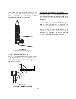


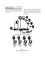


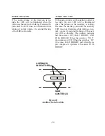


Figure 25
Connecting Two BTR-200 Together
CONNECTING AUXILIARY AUDIO SYSTEM
Connect the BTR-200 to your auxiliary audio
via the Auxiliary input/output receptacles on
the rear of the unit or when two BTR-200 are
used as a system.
Connect the first BTR-200 to the second
BTR-200 by using two short male to female
XLR type cables (not supplied). See Figure 25.
Note that the stations need to be on different
frequencies.
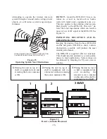
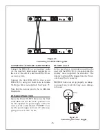
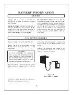
POWER CONNECTION
Insure the Power ON/OFF Switch on the front
of the BTR-200 is in the “OFF” position. Con-
nect the supplied AC power supply cord to the
receiver at the socket labeled “POWER”. Con-
nect the power supply unit to an AC outlet sup-
plying 105 to 125 VAC, 60 Hz.
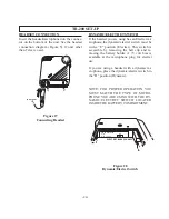
DUMMY LOAD
In the case where a wired intercom will not be
used with the BTR-200, it is important that the
dummy load (supplied) be
installed. The
dummy load should be plugged into the
“Inter-
com Loop-Thru” connector.
NOTE:
If this is not set up properly, an annoy-
ing squeal may result that may cause damage
to the ears.
Figure 26
Connecting the Power Supply
-23-
PUSH
XXXX
XXXX
PUSH
I/C
PUSH
XXXX
XXXX
PUSH
I/C
U
AC/DC 13 OV 300mA
POWER
TO
AC
OUTLET
BTR 200