


Theory of Operation
SPG 422 Service Manual (B034000 and above)
3–23
The microprocessor interface to the Encoder ASIC is essentially done by a bank
of 32 8-bit registers. The Encoder ASIC is mapped into the microprocessor
memory space. Five bits of the external address bus, the external
READ/(WRITE) line, and an address strobe (BLK2) are used to control the
registers. The address strobe, which contains the basic timing information, is
generated whenever the microprocessor accesses those memory locations. The
strobe is used to generate the Encoder ASIC ALE and (CS) signals. The signals
are also decoded and timed by the controller PLD to generate the READ and
WRITE strobes.
Configuration data is written to several of the Encoder ASIC internal registers to
specify the timing offset, standard, etc. The registers also serve as the porthole
through which the segment memories are diagnosed and initialized. At power on,
the configuration data is written to the registers and the segment data is read
from the EPROM and written to the RAM. Subsequent changes to the signals are
just made by changing the configuration data written to the registers.
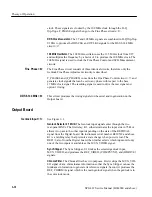
DAC and Output Filter and Driver.
Finally, the over sampled black signal data is
fed to the output circuitry. The DAC and output section convert the digital
representation of black burst to analog, reconstruct and filter the signal, and
buffer it to drive 75
W
.
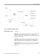
Option 2 Board
The Option 2 board produces the additional serial digital test signals that are
available when Option 2 is installed in the SPG 422. the circuitry is identical to
the Bars generation in the standard instrument.
The Test Signal Generator is a complete generator, requiring only a master clock,
(STSGCLK); a synchronous frame reset, (STSS) or (STSR); and some setup
information from the microprocessor. On startup, the processor writes the signal
configuration information to the generator and downloads the necessary audio
and video test signals into RAM.
Horizontal, Vertical, and Field Counters and Decoding PLDs.
U9 and U10 are the
Horizontal, Vertical, and Field Counters and Decoding PLDs.
The clock and reset drive the counter chain. The counter drives state machines
that select the proper test signal RAM address at the correct time in the field.
Timing Reference Signal Generator.
U12 is the Timing Reference Signal (TRS)
Generator. It gets the appropriate TRS data addresses and loads them into the
Serial Bars RAMs so that the data is multiplexed into the video signal.
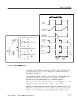
Serial Test Signal
Generation <1>
Summary of Contents for SPG 422
Page 4: ......
Page 14: ...Service Safety Summary x SPG 422 Service Manual B034000 and above ...
Page 17: ......
Page 62: ......
Page 67: ......
Page 92: ......
Page 96: ...Performance Verification 4 4 SPG 422 Service Manual B034000 and above ...
Page 102: ...Performance Verification 4 10 SPG 422 Service Manual B034000 and above ...
Page 136: ...Performance Verification 4 44 SPG 422 Service Manual B034000 and above ...
Page 137: ......
Page 144: ......
Page 158: ...Maintenance 6 14 SPG 422 Service Manual B034000 and above ...
Page 159: ......
Page 162: ......
Page 223: ...9 3 SPG 422 Service Manual SPG 422 Component Digital Sync Generator FRONT PANEL 1 ...
Page 224: ...SPG 422 Service Manual 9 4 ...
Page 226: ...SPG 422 Service Manual 9 6 A2 Digital Board Static Sensitive Devices See Maintenance Section ...
Page 227: ...9 7 SPG 422 Service Manual SPG 422 Component Digital Sync Generator CPU 1 ...
Page 228: ...SPG 422 Service Manual 9 8 A7 Serial Filter ...
Page 229: ...9 9 SPG 422 Service Manual SPG 422 Component Digital Sync Generator CPU I O 2 ...
Page 230: ...SPG 422 Service Manual 9 10 ...
Page 232: ...SPG 422 Service Manual 9 12 ...
Page 234: ...SPG 422 Service Manual 9 14 ...
Page 236: ...SPG 422 Service Manual 9 16 ...
Page 238: ...SPG 422 Service Manual 9 18 ...
Page 239: ...9 19 SPG 422 Service Manual SPG 422 Component Digital Sync Generator 108 MHz OSCILLATOR 7 ...
Page 240: ...SPG 422 Service Manual 9 20 ...
Page 241: ...9 21 SPG 422 Service Manual SPG 422 Component Digital Sync Generator FINE PHASE 8 ...
Page 242: ...SPG 422 Service Manual 9 22 ...
Page 244: ...SPG 422 Service Manual 9 24 ...
Page 250: ...SPG 422 Service Manual 9 30 ...
Page 252: ...SPG 422 Service Manual 9 32 ...
Page 254: ...SPG 422 Service Manual 9 34 ...
Page 256: ...SPG 422 Service Manual 9 36 ...
Page 258: ...SPG 422 Service Manual 9 38 ...
Page 260: ...SPG 422 Service Manual 9 40 ...
Page 264: ...SPG 422 Service Manual 9 44 ...
Page 265: ...9 45 SPG 422 Service Manual 53654 48 1018 2 94 4 7 857 PART OF A5 OPTION 1 BOARD ...
Page 266: ...SPG 422 Service Manual 9 46 ...
Page 268: ...SPG 422 Service Manual 9 48 ...
Page 270: ...SPG 422 Service Manual 9 50 ...
Page 274: ...SPG 422 Service Manual 9 54 ...
Page 276: ...SPG 422 Service Manual 9 56 ...
Page 277: ......
Page 278: ......
Page 286: ...SPG 422 Service Manual 10 8 ...


