


Theory of Operation
3–16
SPG 422 Service Manual (B034000 and above)
select between 110 V and 220 V operation. If J810 is placed on P820, for 220 V
operation, CR820 works as a full-wave rectifier and C845 and C865 act in series,
charging to the peak voltage (approximately 320 VDC) during the first part of
each one-half cycle. They then maintain that voltage through the rest of the
cycle, as the input voltage and current fall to zero.
If, on the other hand, P810 is placed on J810 (for 110 V operation), CR820,
C845, and C865 act as a half-wave rectifier and voltage doubler. During the
positive half-cycle of the AC input only one of the diodes within CR820
conducts, charging C865 to the peak positive voltage. A different diode within
CR820 conducts during the negative half-cycle, and charges C845 to the
negative peak. The total voltage across C845 and C865 is then approximately
320 VDC.
E920 and E820 limit voltage surges on the input that might pass the line filter,
while R865 and R845 discharge C865 and C845 when the power is off. DS720
and associated parts form a relaxation oscillator, so DS720 blinks when the
instrument is powered up. L700, C5, C6, and C700 form a filter to keep noise
developed by the Power Supply from getting onto C865 and C845 and out the
line cord.
These circuits supply the power to start and maintain oscillation of the Pulse
Width Modulator, so long as the input AC voltage is sufficient to maintain
regulation. When the power supply is first turned on, C656 charges through
R921. When the charge across C656 reaches approximately 16 V, U722 begins to
switch Q638 on and off through the base drive circuitry (Q648, and associated
circuits).
The power to maintain the +16 V charge on C656 is now provided by the
housekeeping winding of T1, pins 5 and 6, through CR600. If there is insuffi-
cient power to maintain the charge on C656 for any reason, such as the removal
of P660, then the charge on C656 is quickly depleted. U722 will turn off when
the voltage on C656 drops to approximately 10 V. Then, C656 will slowly
charge again through R921, and the kick start sequence will be repeated. P660
may be used as a troubleshooting jumper, to trigger and verify the kick start
sequence before applying power to T1 through P500.
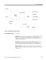
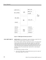
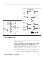
The heart of this power supply is T1, the multi-winding power inductor. The
operation of T1 is as follows (see Figure 3–4). Inductor T1 is initially uncharged
(has zero magnetic flux). Q638, acting as a switch, is turned on by the base drive
from U722. This places the charge developed on C545 and C865 (approximately
320 V) across the primary winding. The polarity of this charge is such that the
voltages induced in the secondaries all reverse bias their respective diodes (note
the polarity dots). In this way, there is no current flowing in the secondaries
while current is flowing in the primary.
Kick Starter, Housekeeping
Supply
Power Inductor Operation
Summary of Contents for SPG 422
Page 4: ......
Page 14: ...Service Safety Summary x SPG 422 Service Manual B034000 and above ...
Page 17: ......
Page 62: ......
Page 67: ......
Page 92: ......
Page 96: ...Performance Verification 4 4 SPG 422 Service Manual B034000 and above ...
Page 102: ...Performance Verification 4 10 SPG 422 Service Manual B034000 and above ...
Page 136: ...Performance Verification 4 44 SPG 422 Service Manual B034000 and above ...
Page 137: ......
Page 144: ......
Page 158: ...Maintenance 6 14 SPG 422 Service Manual B034000 and above ...
Page 159: ......
Page 162: ......
Page 223: ...9 3 SPG 422 Service Manual SPG 422 Component Digital Sync Generator FRONT PANEL 1 ...
Page 224: ...SPG 422 Service Manual 9 4 ...
Page 226: ...SPG 422 Service Manual 9 6 A2 Digital Board Static Sensitive Devices See Maintenance Section ...
Page 227: ...9 7 SPG 422 Service Manual SPG 422 Component Digital Sync Generator CPU 1 ...
Page 228: ...SPG 422 Service Manual 9 8 A7 Serial Filter ...
Page 229: ...9 9 SPG 422 Service Manual SPG 422 Component Digital Sync Generator CPU I O 2 ...
Page 230: ...SPG 422 Service Manual 9 10 ...
Page 232: ...SPG 422 Service Manual 9 12 ...
Page 234: ...SPG 422 Service Manual 9 14 ...
Page 236: ...SPG 422 Service Manual 9 16 ...
Page 238: ...SPG 422 Service Manual 9 18 ...
Page 239: ...9 19 SPG 422 Service Manual SPG 422 Component Digital Sync Generator 108 MHz OSCILLATOR 7 ...
Page 240: ...SPG 422 Service Manual 9 20 ...
Page 241: ...9 21 SPG 422 Service Manual SPG 422 Component Digital Sync Generator FINE PHASE 8 ...
Page 242: ...SPG 422 Service Manual 9 22 ...
Page 244: ...SPG 422 Service Manual 9 24 ...
Page 250: ...SPG 422 Service Manual 9 30 ...
Page 252: ...SPG 422 Service Manual 9 32 ...
Page 254: ...SPG 422 Service Manual 9 34 ...
Page 256: ...SPG 422 Service Manual 9 36 ...
Page 258: ...SPG 422 Service Manual 9 38 ...
Page 260: ...SPG 422 Service Manual 9 40 ...
Page 264: ...SPG 422 Service Manual 9 44 ...
Page 265: ...9 45 SPG 422 Service Manual 53654 48 1018 2 94 4 7 857 PART OF A5 OPTION 1 BOARD ...
Page 266: ...SPG 422 Service Manual 9 46 ...
Page 268: ...SPG 422 Service Manual 9 48 ...
Page 270: ...SPG 422 Service Manual 9 50 ...
Page 274: ...SPG 422 Service Manual 9 54 ...
Page 276: ...SPG 422 Service Manual 9 56 ...
Page 277: ......
Page 278: ......
Page 286: ...SPG 422 Service Manual 10 8 ...


