


Theory of Operation
SPG 422 Service Manual (B034000 and above)
3–3
Digital Board
The Digital Board CPU consists of the microprocessor and its associated
memory and buffers.
The Ground Closure Parallel Remote consists of a latch that samples the remote
data and places it on the external data bus whenever it is polled by the micropro-
cessor.
The microprocessor sends data over the external data bus for conversion into
driver signals for the front-panel LEDs.
The Display Data Latch consists of two parts. The first gets data from the
external data bus and converts it into an analog voltage that controls the contrast
of the front-panel display. The second part controls the actual characters
displayed on screen.
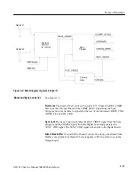
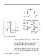
The Test Signal Generator is a complete generator, requiring only a master clock,
a synchronous frame reset, and setup information from the microprocessor. On
startup, the processor writes the signal configuration information to the generator
and downloads the necessary audio and video test signals into RAM.
Audio RAM data is the audio tone formatted in a specific format for AES audio.
This data is read from the Audio RAMs at a particular point in the video data
stream to be embedded. The audio data is placed into RAM by the microproces-
sor.
Controlled by signals from the CPU, the Genlock Type Selector selects
which
type of genlock signal to expect. The selected signal is then converted and used
as the correction signal for the VCXO.
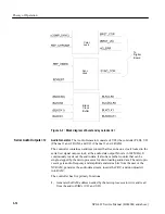
The heart of the VCXO is the Oven Oscillator Assembly, which takes the VCXO
correction signal and a reference voltage to produce a 13.5 MHz instrument
clock signal that is phase locked to the genlock input signal. All other timing
signals are derived from this main reference clock signal.
Any errors with the oscillator are flagged with LEDs.
The main purpose of the Direct Digital Synthesizer is to produce the clock for
the Burst Lock circuit and the edge strobe for the Sync Lock circuit.
The 108 MHz oscillator steps up the 13.5 MHz instrument clock to produce a
27 MHz clock and a 108 MHz clock.
The 27 MHz clock is used by the Genlock Controller and DDS. The Fine Phase
and SCH measurement circuits use the 108 MHz.
The Fine Phase circuit consists of four identical circuits. The resulting signal is
used to drive the test signal and option 1 timing.
Summary of Contents for SPG 422
Page 4: ......
Page 14: ...Service Safety Summary x SPG 422 Service Manual B034000 and above ...
Page 17: ......
Page 62: ......
Page 67: ......
Page 92: ......
Page 96: ...Performance Verification 4 4 SPG 422 Service Manual B034000 and above ...
Page 102: ...Performance Verification 4 10 SPG 422 Service Manual B034000 and above ...
Page 136: ...Performance Verification 4 44 SPG 422 Service Manual B034000 and above ...
Page 137: ......
Page 144: ......
Page 158: ...Maintenance 6 14 SPG 422 Service Manual B034000 and above ...
Page 159: ......
Page 162: ......
Page 223: ...9 3 SPG 422 Service Manual SPG 422 Component Digital Sync Generator FRONT PANEL 1 ...
Page 224: ...SPG 422 Service Manual 9 4 ...
Page 226: ...SPG 422 Service Manual 9 6 A2 Digital Board Static Sensitive Devices See Maintenance Section ...
Page 227: ...9 7 SPG 422 Service Manual SPG 422 Component Digital Sync Generator CPU 1 ...
Page 228: ...SPG 422 Service Manual 9 8 A7 Serial Filter ...
Page 229: ...9 9 SPG 422 Service Manual SPG 422 Component Digital Sync Generator CPU I O 2 ...
Page 230: ...SPG 422 Service Manual 9 10 ...
Page 232: ...SPG 422 Service Manual 9 12 ...
Page 234: ...SPG 422 Service Manual 9 14 ...
Page 236: ...SPG 422 Service Manual 9 16 ...
Page 238: ...SPG 422 Service Manual 9 18 ...
Page 239: ...9 19 SPG 422 Service Manual SPG 422 Component Digital Sync Generator 108 MHz OSCILLATOR 7 ...
Page 240: ...SPG 422 Service Manual 9 20 ...
Page 241: ...9 21 SPG 422 Service Manual SPG 422 Component Digital Sync Generator FINE PHASE 8 ...
Page 242: ...SPG 422 Service Manual 9 22 ...
Page 244: ...SPG 422 Service Manual 9 24 ...
Page 250: ...SPG 422 Service Manual 9 30 ...
Page 252: ...SPG 422 Service Manual 9 32 ...
Page 254: ...SPG 422 Service Manual 9 34 ...
Page 256: ...SPG 422 Service Manual 9 36 ...
Page 258: ...SPG 422 Service Manual 9 38 ...
Page 260: ...SPG 422 Service Manual 9 40 ...
Page 264: ...SPG 422 Service Manual 9 44 ...
Page 265: ...9 45 SPG 422 Service Manual 53654 48 1018 2 94 4 7 857 PART OF A5 OPTION 1 BOARD ...
Page 266: ...SPG 422 Service Manual 9 46 ...
Page 268: ...SPG 422 Service Manual 9 48 ...
Page 270: ...SPG 422 Service Manual 9 50 ...
Page 274: ...SPG 422 Service Manual 9 54 ...
Page 276: ...SPG 422 Service Manual 9 56 ...
Page 277: ......
Page 278: ......
Page 286: ...SPG 422 Service Manual 10 8 ...


