


Theory of Operation
3–18
SPG 422 Service Manual (B034000 and above)
Q638 is turned back on to start the next cycle. As there is not a continuous flow
of energy in T1, this is called discontinuous flyback operation. At low line
voltages or high loads all the power in inductor T1 may not be transferred to the
load during the second half of the cycle, in which case the diodes will not be off
when Q638 turns back on. In that case there will also be some energy still stored
in T1 at the end of the cycle (at low line or high load).
Load regulation is provided by sensing the +5 V supply with a divider comprised
by R314, R315, and R415, and using U410 to convert this to an error signal.
This error signal is optically coupled through U520 back to the Pulse Width
Modulator, U722. U722 uses the error signal to vary the width of the pulse that
drives Q638.
When the +5 V goes too high, U722 narrows the pulse width. This reduces the
amount of energy stored in T1, and therefore the amount transferred to the load,
so the +5 V goes down. Contrariwise, when the +5 V is too low, the pulse width
is increased, increasing the amount of energy stored in T1 and then transferred to
the load, so the voltage goes up.
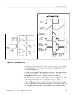
See Figure 3–5.
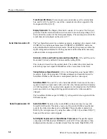
The Pulse Width Modulator, U722, is a current-mode controller. It uses inputs
from the primary circuit and from the +5 V output to vary the width of the pulse
that controls Q638, as mentioned above. This regulates the secondary voltages
throughout variations such as input voltage, output load, and temperature.
Current mode control works by allowing the current flowing in the primary to
reach a peak level that is set by the output of the error amp (internal to U722),
which is controlled by the +5 V output. The current in the primary winding is
sensed by R630, and applied to U722-3 as a voltage. At the start of the cycle the
oscillator sets the flip-flop within U722, which turns Q638 on. The primary
current, and therefore the voltage to U722-3, ramps up until the I - SENSE level
is sufficient to trip the comparator. This resets the flip-flop, ending the drive
pulse to Q638, and the energy stored in the transformer is transferred to the
secondaries.
Line regulation is accomplished automatically without voltage feedback. As the
input voltage increases, the slope of the ramp increases, and the trip point is
reached sooner. This results in a shorter pulse width. A decrease in line voltage
causes a decrease in the slope of the ramp, and it takes longer to reach the trip
point. The same peak current is reached in both cases, however, so the same
amount of energy is transferred to the load. Line regulation, then, is achieved
before variations in output voltage can occur.
Pulse Width Modulator
and Error Amplifier
Summary of Contents for SPG 422
Page 4: ......
Page 14: ...Service Safety Summary x SPG 422 Service Manual B034000 and above ...
Page 17: ......
Page 62: ......
Page 67: ......
Page 92: ......
Page 96: ...Performance Verification 4 4 SPG 422 Service Manual B034000 and above ...
Page 102: ...Performance Verification 4 10 SPG 422 Service Manual B034000 and above ...
Page 136: ...Performance Verification 4 44 SPG 422 Service Manual B034000 and above ...
Page 137: ......
Page 144: ......
Page 158: ...Maintenance 6 14 SPG 422 Service Manual B034000 and above ...
Page 159: ......
Page 162: ......
Page 223: ...9 3 SPG 422 Service Manual SPG 422 Component Digital Sync Generator FRONT PANEL 1 ...
Page 224: ...SPG 422 Service Manual 9 4 ...
Page 226: ...SPG 422 Service Manual 9 6 A2 Digital Board Static Sensitive Devices See Maintenance Section ...
Page 227: ...9 7 SPG 422 Service Manual SPG 422 Component Digital Sync Generator CPU 1 ...
Page 228: ...SPG 422 Service Manual 9 8 A7 Serial Filter ...
Page 229: ...9 9 SPG 422 Service Manual SPG 422 Component Digital Sync Generator CPU I O 2 ...
Page 230: ...SPG 422 Service Manual 9 10 ...
Page 232: ...SPG 422 Service Manual 9 12 ...
Page 234: ...SPG 422 Service Manual 9 14 ...
Page 236: ...SPG 422 Service Manual 9 16 ...
Page 238: ...SPG 422 Service Manual 9 18 ...
Page 239: ...9 19 SPG 422 Service Manual SPG 422 Component Digital Sync Generator 108 MHz OSCILLATOR 7 ...
Page 240: ...SPG 422 Service Manual 9 20 ...
Page 241: ...9 21 SPG 422 Service Manual SPG 422 Component Digital Sync Generator FINE PHASE 8 ...
Page 242: ...SPG 422 Service Manual 9 22 ...
Page 244: ...SPG 422 Service Manual 9 24 ...
Page 250: ...SPG 422 Service Manual 9 30 ...
Page 252: ...SPG 422 Service Manual 9 32 ...
Page 254: ...SPG 422 Service Manual 9 34 ...
Page 256: ...SPG 422 Service Manual 9 36 ...
Page 258: ...SPG 422 Service Manual 9 38 ...
Page 260: ...SPG 422 Service Manual 9 40 ...
Page 264: ...SPG 422 Service Manual 9 44 ...
Page 265: ...9 45 SPG 422 Service Manual 53654 48 1018 2 94 4 7 857 PART OF A5 OPTION 1 BOARD ...
Page 266: ...SPG 422 Service Manual 9 46 ...
Page 268: ...SPG 422 Service Manual 9 48 ...
Page 270: ...SPG 422 Service Manual 9 50 ...
Page 274: ...SPG 422 Service Manual 9 54 ...
Page 276: ...SPG 422 Service Manual 9 56 ...
Page 277: ......
Page 278: ......
Page 286: ...SPG 422 Service Manual 10 8 ...


