


Theory of Operation
SPG 422 Service Manual (B034000 and above)
3–15
Power Supply
The switching power supply generates 5 V for TTL and ECL devices. A stable
linear supply of 12 V is provided for powering the analog circuitry.
This type of power supply is called a current-mode-controlled, discontinuous,
flyback, switching power supply. The current output is distributed between the
four supplies as follows:
+ 12 V
0.8 Amps max
+5 V
7 Amps max
-5 V
6 Amps max
-12 V
0.8 Amps max
The maximum power is limited by the maximum current in the primary of T1.
This is also the only current limit for the
±
5 V supplies, as they have no
secondary current limit. The
±
12 V supplies are current limited on the second-
aries by the
±
12 V linear regulators, U150 and U152, and the secondary
±
14.5
pulse width modulator, U200.
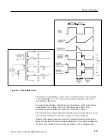
The power inductor, T1, is driven by switching the voltage to its primary
winding on and off at a rate of approximately 60 kHz. T1 is not used as a
transformer, but as an energy storage device; the energy is stored in the primary
during the first half of the switching cycle, while voltage is being applied. On the
second half of the switching cycle, voltage to the primary is switched off and the
energy stored in T1 is transferred to the secondaries. Regulation is accomplished
by feedback from the +5 V supply to the Pulse Width Modulator controlling
voltage to the primary. This varies the length of time that voltage is applied to
the primary, causing it to store either more or less energy.
There is also circuitry to provide for operation from both 110 and 220 VAC
supplies, over voltage protection (crowbar) on the +5 V supply, and shutdown
circuitry that forces a restart of the supply if it remains in current limit for more
than a short period of time < 200 ms).
WARNING.
All primary voltages are referenced to a floating ground, not chassis
ground. An isolation transformer or a differential amplifier is therefore required
for troubleshooting the circuitry in the primary and the Pulse Width Modulator,
and in the supporting circuits. Potentials to chassis ground can be much higher
and the possibility exists that you could electrocute yourself.
This circuitry filters and rectifies the input AC voltage, charging capacitors C845
and C865 to approximately 320 VDC.
The line current passes through line filter LF950, fuse F940, and power switch
S930, and is applied to rectifier CR820. At the input of CR820, P810 is used to
Input, AC to DC Converter,
and Voltage Double
r
Summary of Contents for SPG 422
Page 4: ......
Page 14: ...Service Safety Summary x SPG 422 Service Manual B034000 and above ...
Page 17: ......
Page 62: ......
Page 67: ......
Page 92: ......
Page 96: ...Performance Verification 4 4 SPG 422 Service Manual B034000 and above ...
Page 102: ...Performance Verification 4 10 SPG 422 Service Manual B034000 and above ...
Page 136: ...Performance Verification 4 44 SPG 422 Service Manual B034000 and above ...
Page 137: ......
Page 144: ......
Page 158: ...Maintenance 6 14 SPG 422 Service Manual B034000 and above ...
Page 159: ......
Page 162: ......
Page 223: ...9 3 SPG 422 Service Manual SPG 422 Component Digital Sync Generator FRONT PANEL 1 ...
Page 224: ...SPG 422 Service Manual 9 4 ...
Page 226: ...SPG 422 Service Manual 9 6 A2 Digital Board Static Sensitive Devices See Maintenance Section ...
Page 227: ...9 7 SPG 422 Service Manual SPG 422 Component Digital Sync Generator CPU 1 ...
Page 228: ...SPG 422 Service Manual 9 8 A7 Serial Filter ...
Page 229: ...9 9 SPG 422 Service Manual SPG 422 Component Digital Sync Generator CPU I O 2 ...
Page 230: ...SPG 422 Service Manual 9 10 ...
Page 232: ...SPG 422 Service Manual 9 12 ...
Page 234: ...SPG 422 Service Manual 9 14 ...
Page 236: ...SPG 422 Service Manual 9 16 ...
Page 238: ...SPG 422 Service Manual 9 18 ...
Page 239: ...9 19 SPG 422 Service Manual SPG 422 Component Digital Sync Generator 108 MHz OSCILLATOR 7 ...
Page 240: ...SPG 422 Service Manual 9 20 ...
Page 241: ...9 21 SPG 422 Service Manual SPG 422 Component Digital Sync Generator FINE PHASE 8 ...
Page 242: ...SPG 422 Service Manual 9 22 ...
Page 244: ...SPG 422 Service Manual 9 24 ...
Page 250: ...SPG 422 Service Manual 9 30 ...
Page 252: ...SPG 422 Service Manual 9 32 ...
Page 254: ...SPG 422 Service Manual 9 34 ...
Page 256: ...SPG 422 Service Manual 9 36 ...
Page 258: ...SPG 422 Service Manual 9 38 ...
Page 260: ...SPG 422 Service Manual 9 40 ...
Page 264: ...SPG 422 Service Manual 9 44 ...
Page 265: ...9 45 SPG 422 Service Manual 53654 48 1018 2 94 4 7 857 PART OF A5 OPTION 1 BOARD ...
Page 266: ...SPG 422 Service Manual 9 46 ...
Page 268: ...SPG 422 Service Manual 9 48 ...
Page 270: ...SPG 422 Service Manual 9 50 ...
Page 274: ...SPG 422 Service Manual 9 54 ...
Page 276: ...SPG 422 Service Manual 9 56 ...
Page 277: ......
Page 278: ......
Page 286: ...SPG 422 Service Manual 10 8 ...


