


Theory of Operation
SPG 422 Service Manual (B034000 and above)
3–21
The
±
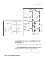
12 V supplies are generated with a secondary PWM and regulator
composed of U200, Q250, T2, and the associated circuits. This secondary PWM
is free-running with respect to the primary PWM at a frequency of approximately
60 kHz. The frequency is set by R105 and C105. Q250 is controlled by U200 to
5 V and -5 V (10 Volts total) across T2 during the first half of the
switching cycle. During the second half of the cycle, the voltage across T2
reverses and CR150 and CR160 turn on, causing a charge to build up on C150
and C152. The voltage on C150 is regulated by U200 to be approximately
+14.5 V, and the voltage on C152 will follow at approximately -14.5 V. The
14.5 V is then filtered by L150 and L162, respectively, and applied to the three
terminal linear regulators (U150 and U152) to derive the + 12 V and -12 V
outputs.
R260 senses the current in T2 and feeds it back as a voltage to U200-3. Q200
applies part of the ramp voltage on U200-4 through R125 to U200-3 for better
noise immunity.
Q100 is in the voltage feedback path for the +14.5 volts and acts as a level
shifter to get the voltage feedback signal to a level referenced at + 2.5 V with
respect to U200-5. U200-5 is at -5 V with respect to ground. P800 disables the
operation of U200 and turns Q250 off. With U200 disabled, the
±
14.5 V outputs
will go to
±
5 volts. Jumper P800 is provided for troubleshooting. Its removal
will disable the
±
12 V PWM, which may be necessary for diagnosis or repair of
the primary portion of the power supply.
Over voltage protection is provided on the +5 V output by a crowbar circuit
composed of Q127, VR120, and R120. If the +5 V output exceeds approximately
+5.5 V, VR120 will start to conduct. When VR120 is drawing enough current
through R120 to raise SCR Q127 gate voltage above its cathode by approximate-
ly 0.7 V, Q127 will turn on. This shorts the +5 V output to ground, forcing the
primary circuit into current limit.
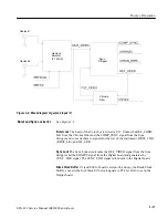
Option 1 Board
The SPG 422 Option 1 board contains four separate dual-standard black
generators. Each is a separate generator running on a 27 MHz master clock, with
PAL and NTSC frame resets to synchronize them and some microprocessor setup
information to program them.
All black burst generators are identical. The following paragraphs describe black
burst generator 3.
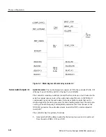
Controller PLD.
The four black generators are controlled by the microprocessor
and the Controller PLD, U2. The Controller PLD takes the video standard
selection for each channel and selects and processes the appropriate frame reset
Generating 12 Volts
Over Voltage Protection
Black burst generator
<1>, <2>, <3>, and <4>
Summary of Contents for SPG 422
Page 4: ......
Page 14: ...Service Safety Summary x SPG 422 Service Manual B034000 and above ...
Page 17: ......
Page 62: ......
Page 67: ......
Page 92: ......
Page 96: ...Performance Verification 4 4 SPG 422 Service Manual B034000 and above ...
Page 102: ...Performance Verification 4 10 SPG 422 Service Manual B034000 and above ...
Page 136: ...Performance Verification 4 44 SPG 422 Service Manual B034000 and above ...
Page 137: ......
Page 144: ......
Page 158: ...Maintenance 6 14 SPG 422 Service Manual B034000 and above ...
Page 159: ......
Page 162: ......
Page 223: ...9 3 SPG 422 Service Manual SPG 422 Component Digital Sync Generator FRONT PANEL 1 ...
Page 224: ...SPG 422 Service Manual 9 4 ...
Page 226: ...SPG 422 Service Manual 9 6 A2 Digital Board Static Sensitive Devices See Maintenance Section ...
Page 227: ...9 7 SPG 422 Service Manual SPG 422 Component Digital Sync Generator CPU 1 ...
Page 228: ...SPG 422 Service Manual 9 8 A7 Serial Filter ...
Page 229: ...9 9 SPG 422 Service Manual SPG 422 Component Digital Sync Generator CPU I O 2 ...
Page 230: ...SPG 422 Service Manual 9 10 ...
Page 232: ...SPG 422 Service Manual 9 12 ...
Page 234: ...SPG 422 Service Manual 9 14 ...
Page 236: ...SPG 422 Service Manual 9 16 ...
Page 238: ...SPG 422 Service Manual 9 18 ...
Page 239: ...9 19 SPG 422 Service Manual SPG 422 Component Digital Sync Generator 108 MHz OSCILLATOR 7 ...
Page 240: ...SPG 422 Service Manual 9 20 ...
Page 241: ...9 21 SPG 422 Service Manual SPG 422 Component Digital Sync Generator FINE PHASE 8 ...
Page 242: ...SPG 422 Service Manual 9 22 ...
Page 244: ...SPG 422 Service Manual 9 24 ...
Page 250: ...SPG 422 Service Manual 9 30 ...
Page 252: ...SPG 422 Service Manual 9 32 ...
Page 254: ...SPG 422 Service Manual 9 34 ...
Page 256: ...SPG 422 Service Manual 9 36 ...
Page 258: ...SPG 422 Service Manual 9 38 ...
Page 260: ...SPG 422 Service Manual 9 40 ...
Page 264: ...SPG 422 Service Manual 9 44 ...
Page 265: ...9 45 SPG 422 Service Manual 53654 48 1018 2 94 4 7 857 PART OF A5 OPTION 1 BOARD ...
Page 266: ...SPG 422 Service Manual 9 46 ...
Page 268: ...SPG 422 Service Manual 9 48 ...
Page 270: ...SPG 422 Service Manual 9 50 ...
Page 274: ...SPG 422 Service Manual 9 54 ...
Page 276: ...SPG 422 Service Manual 9 56 ...
Page 277: ......
Page 278: ......
Page 286: ...SPG 422 Service Manual 10 8 ...


