background image

Taking Measurements

3- 110

YBT250 Field Transmitter & Interference Tester User Manual

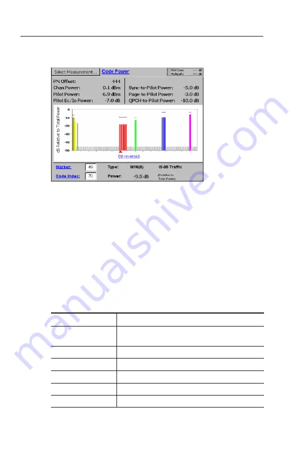
Figure 3- 53: cdma2000 Code Power display

6.

To select which marker to measure, do either of the following:

H

Tap the entry field next to the Marker readout. Then use the
knob or the numeric keypad to enter a marker number.

H

Tap the graph to assign the knob or the numeric keypad to
enter a marker number.

Table 3--21 describes the cdma2000 Code Domain measurements.

Table 3- 21: cdma2000 Code Domain measurement fields

Field

Description

PN Offset

The coarse timing difference, in chips, between the
pilot channel and the even second clock.

Chan Power

The total RF power in the selected channel.

Pilot Power

The absolute power of the CDMA signal’s pilot code.

Pilot Ec/Io Power

The Pilot Power minus the Channel Power.

Sync-to-Pilot Power

The Sync Channel Power minus the Pilot Power.

Page-to-Pilot Power

The Page Channel Power minus the Pilot Power.

Summary of Contents for NetTek YBT250

Page 1: ...User Manual NetTekR YBT250 Field Transmitter Interference Tester 071 0856 14 This document supports firmware version 1 654 and above www tektronix com...

Page 2: ...pending Information in this publication supercedes that in all previously published material Specifications and price change privileges reserved TEKTRONIX TEK and NetTek are registered trademarks of T...

Page 3: ...ed Customer shall be responsible for paying all shipping charges duties taxes and any other charges for products returned to any other locations This warranty shall not apply to any defect failure or...

Page 4: ......

Page 5: ...Installing or Removing a Battery 1 7 Charging a Battery 1 9 Maximizing Battery Operating Time 1 10 Transporting Lithium Ion Batteries 1 10 Battery Recycling 1 10 Powering On the Instrument 1 11 How t...

Page 6: ...easurement Area 2 12 Using the Touch Screen 2 12 Using the Knob 2 13 Using the Numeric Keypad 2 13 YBT250 Menus 2 13 Entering Text 2 18 Connecting a Signal 2 21 YBT250 Inputs 2 21 RF Signal Input 2 22...

Page 7: ...Receiver Field 2 54 GPS Field 2 54 GPS Status Field 2 54 GPS Information Field 2 56 GPS Satellite Signal Strength Field 2 57 Saving GPS Data with Measurements 2 58 Troubleshooting Your GPS Receiver 2...

Page 8: ...erfering Signal 3 41 Measuring the Noise Floor 3 43 Locating Intermittent Interference 3 44 W CDMA Scrambling Code Analyzer 3 47 Sorting or Locking Scrambling Codes 3 49 cdma2000 and 1xEV DO PN Scanne...

Page 9: ...y 3 103 Setting cdma2000 or 1xEV DO PN Offset 3 106 Measuring 1xEV DO Code Power 3 107 Measuring cdma2000 Code Power 3 109 Measuring cdmaOne Code Power 3 112 Measuring W CDMA Code Power 3 114 Setting...

Page 10: ...ng a Trace 3 147 Recalling a Trace 3 147 Exporting a Trace 3 148 Differences Between Exported Screens and Traces 3 149 Saving Setups 3 152 Recalling Setups 3 153 Customizing the Setup menu 3 153 Preve...

Page 11: ...nual vii Appendix E Functional Verification Procedure E 1 Self Tests E 1 Functional Tests E 3 Appendix F Supported Signal Standards F 1 Appendix G Channel Table Definition File G 1 About the Signal Ty...

Page 12: ...Table of Contents viii YBT250 Field Transmitter Interference Tester User Manual...

Page 13: ...product and certified for the country of use Connect and Disconnect Properly Do not connect or disconnect probes or test leads while they are connected to a voltage source Observe All Terminal Rating...

Page 14: ...dentify conditions or practices that could result in injury or loss of life CAUTION Caution statements identify conditions or practices that could result in damage to this product or other property Te...

Page 15: ...led appropriately The symbol shown to the left indicates that this product complies with the European Union s requirements according to Directive 2002 96 EC on waste electrical and electronic equipmen...

Page 16: ...rence Tester User Manual Restriction of Hazardous Substances This product has been classified as Monitoring and Control equipment and is outside the scope of the 2002 95 EC RoHS Directive This product...

Page 17: ...Field Transmitter Interference Tester has powerful analysis tools to enable you to locate and identify interfering signals quickly With its built in spectrum analysis display the YBT250 enables you t...

Page 18: ...operating the NetTek Analyzer Platform is contained in the Getting Started section of this manual Conventions This manual uses the following convention The statement Start Help is requesting that you...

Page 19: ...Getting Started...

Page 20: ......

Page 21: ...alyzer Platform layout Figure 1 2 shows the front panel controls and indicators Figure 1 3 shows the input and output ports Batteries Application modules PC card Front panel External power I O ports T...

Page 22: ...rdware reset if a lock up occurs All programs and data loaded into volatile memory since power on are lost 3 Status Indicator Green indicates that the instrument is powered on Amber indicates that the...

Page 23: ...erence Tester User Manual 1 3 1 2 3 4 5 6 7 Figure 1 3 I O ports Y400 NetTek Analyzer Platform 1 Microphone input 2 Headphone jack 3 Ethernet connector RJ 45 4 Serial port RS 232 5 PS 2 keyboard conne...

Page 24: ...lyzer platform before you can take measurements Refer to Figures 1 4 and 1 5 to install or remove an application module CAUTION To prevent damage to the NetTek Analyzer Platform or an application modu...

Page 25: ...e the coin slot in the top of the thumb screw if you require additional torque Tighten all screws evenly but do not overtighten To install additional modules up to three remove the bus cover from the...

Page 26: ...er Platform from AC mains or DC vehicle voltage or recharge installed batteries connect the Desktop Power Supply or the In Vehicle Adapter to the NetTek Analyzer Platform as shown in Figure 1 6 The De...

Page 27: ...s shipped Refer to Figures 1 7 through 1 9 for battery installation or removal steps NOTE Disconnect power supply cables from the NetTek Analyzer Platform before installing or removing batteries New b...

Page 28: ...he battery retainer tab down and towards the back of instrument then lift 2 Rotate the battery retainer upward Figure 1 8 Opening the battery retainer Battery retainer in open position Install battery...

Page 29: ...ge batteries connect the instrument to an external power supply see Figure 1 6 on page 1 6 and let the battery or batteries recharge in the instrument Table 1 1 lists the approximate charge times for...

Page 30: ...ximizing Battery Operating Time For tips on how to maximize battery operating time select Start Help Settings Power Management Optimizing Battery Life Transporting Lithium Ion Batteries Regulations re...

Page 31: ...lash memory available then the application module software loads into volatile memory this happens only with user installed modules if your application module was purchased already installed on a NetT...

Page 32: ...separate but related standby and power off functions Suspend Mode Use Suspend mode to place the NetTek Analyzer Platform in a suspended standby or sleep state This is the typical power down mode that...

Page 33: ...Start Help 2 In the Help window select Tektronix Basics 3 Select Store Data in Nonvolatile Memory The next time you press the front panel power switch the NetTek Analyzer Platform cycles through the c...

Page 34: ...H If the analyzer is in PowerSaver mode touch screen display off activates the display Preventing Personal Injury from the Effects of Lightning WARNING To prevent personal injury from the effects of l...

Page 35: ...tning H When lightning strikes a structure or facility current travels through the rebar concrete pipes cables vent stacks and electrical system H Lightning can induce electric and magnetic fields int...

Page 36: ...Setting Up the Tilt Stand For floor or desktop use attach the tilt stand to the NetTek Analyzer Platform and fold into place See Figure 1 10 Attach tilt stand with thumb screws 3 Bottom thumb screw l...

Page 37: ...e 1 11 You can store cables and other accessories such as the NetTek YBGPS1 GPS Timing Reference receiver in the spacer compart ment Each additional module installed requires a module storage spacer w...

Page 38: ...1 12 You can also install the strap on the soft case Use the Strand hook to hang the instrument from a wire strand ladder or other support Install the strand hook as shown in Figure 1 12 CAUTION The...

Page 39: ...Operating Basics...

Page 40: ......

Page 41: ...four instrument modules it is a highly flexible instrument that can be reconfigured to meet your changing needs The NetTek Analyzer Platform is a specialized Windows CE based computer The NetTek Analy...

Page 42: ...the top level of the YBT250 help H Tap underlined text on the screen This displays the Help topic for that item H Display Help from some dialog boxes by tapping the Help button in the bottom right cor...

Page 43: ...y workspace Use the desktop to configure hardware and software adjust settings establish communications and access built in applications Taskbar Desktop Icon Icons Double tap desktop icons to open fol...

Page 44: ...he menu Program Buttons To hide a program that is running tap its taskbar button To restore the program tap the button again Status Area Icons and buttons appearing in this area indicate status activa...

Page 45: ...ity The analyzer is charging batteries Double tap to open the Power Management utility The analyzer is operating on battery power Also indicates charge level Double tap to open the Backlight utility A...

Page 46: ...d your YBT250 module to a NetTek Analyzer Platform you already own see page 2 7 for instructions on how to start the YBT250 software or set the software to load at startup To start the YBT250 software...

Page 47: ...ou can set the YBT250 to load at startup To set the YBT250 as the startup application 1 Select Start Programs Tektronix Utilities System Configuration 2 On the Software tab select the StartUp checkbox...

Page 48: ...itter Interference Tester display Measurement area Shared control area Tuning controls Command bar area Figure 2 3 YBT250 display elements H Tuning Controls Area This area contains the controls used t...

Page 49: ...Function Indicates the overall GPS signal quality Tapping this button opens the GPS tab for selecting GPS receiver type and other GPS related settings Shows the measurement frequency reference source...

Page 50: ...vides a way to display multiple measurement results in a single window This area shows the control assigned to the knob and the value of that control The Keypad button enables you to enter numbers usi...

Page 51: ...T250 is acquiring measure ments Shown when displaying recalled data Opens the instrument Online Help Tuning Control Area Table 2 5 describes the Tuning Control Area elements left to right Table 2 5 Tu...

Page 52: ...to use the numeric keypad tap the box to use the knob Measurement Area Icons and buttons in the Measurement Area change depending on the function selected by the Shared Control buttons H For descript...

Page 53: ...bove the control knob 3 Type the new value including units when present 4 Tap OK when present to accept the new value YBT250 Menus The YBT250 menu bar has four menus These menus are File View Setup an...

Page 54: ...sults to a file displays Save dialog box so you can name the file and specify where it is saved Compare Saved Display two saved results for visual comparison Disabled Export Results As Save measuremen...

Page 55: ...re Trace in a file displays Save dialog box to enable you to name the file and specify where it is saved Compare Saved Display two saved results for visual comparison Export Trace As Store Trace in a...

Page 56: ...Testing Define Mask Displays the Trace 2 Mask tab of the Setup window enabling you to specify the mask file to use for mask testing and any action to perform on mask failure Markers Ctrl M Displays H...

Page 57: ...equency range Saved Setup 1 N Name of most recently used setup files or files specified in Tools Options Settings Menu Up to 10 files can be displayed Table 2 10 describes the elements of the Tools me...

Page 58: ...formation Software Info Displays the SW Properties window which lists among other things the installed options Options key and software version Hardware Info Displays the HW Properties window which li...

Page 59: ...rference Tester User Manual 2 19 Figure 2 4 The Soft Keyboard To set soft keyboard properties or switch between a large keyboard default and a smaller keyboard select Start Settings Control Panel Open...

Page 60: ...Operating Basics 2 20 YBT250 Field Transmitter Interference Tester User Manual...

Page 61: ...rference Tester YBT250 Inputs Figure 2 5 identifies the YBT250 Field Transmitter Interference Tester inputs 1 2 3 Figure 2 5 YBT250 inputs 1 The Timing Input connects to an external timing reference s...

Page 62: ...surement and the installed options See Appendix A Specifications for the appropriate input signal levels for specific combinations of measurements and installed options To measure a signal with very h...

Page 63: ...mage the input circuitry 3 If the transmitter output signal level is too low see the specifications in Appendix A connect the transmitter output signal to an external amplifier and then connect the ou...

Page 64: ...lect External attenuator connected Tap the numeric keypad and enter the attenuator loss value For example if you are using a 20 dB attenuator tap 20 on the numeric keypad and then tap OK d If you are...

Page 65: ...ut being attached to the BTS ESC signal If Option CS1 is installed the YBT250 can also make cdma2000 over the air OTA measurements Improving Measurement Accuracy There are three ways to improve YBT250...

Page 66: ...BTS equipment 10 MHz Standard frequency from WWV and other high accuracy references 13 MHz For GSM systems 15 MHz For Lucent W CDMA 1 MHz 2 MHz 5 MHz Along with 10 MHz these are standard for Rubidium...

Page 67: ...Figure 2 8 shows typical external frequency reference input displays for an external signal upper image and for when a NetTek YBGPS1 GPS Timing Reference is con nected Figure 2 8 External frequency r...

Page 68: ...values or the original factory generated values when at a remote site CAUTION You should run the Frequency Correction utility only if you have a known high quality Reference source The Reference sourc...

Page 69: ...terference Tester User Manual 2 29 Figure 2 9 The Frequency Correction dialog 4 To calculate new frequency correction values tap Run New Correction This displays the dialog shown in Figure 2 10 Figure...

Page 70: ...equency is not displayed within 15 seconds check the connection to the external frequency reference 5 If the reference frequency is detected tap Finish to calculate new frequency correction values If...

Page 71: ...cting a Signal YBT250 Field Transmitter Interference Tester User Manual 2 31 Figure 2 12 The Frequency Correction dialog 7 To use the new frequency correction values select Use Corrected Values then t...

Page 72: ...Connecting a Signal 2 32 YBT250 Field Transmitter Interference Tester User Manual...

Page 73: ...ted signal standard controls the channels available for measurements and which measurements are available Before you begin using the YBT250 you must ensure that the standard for your system has been e...

Page 74: ...ield 5 When you have enabled all the standards you will be testing tap OK Only enabled standards are selectable from the signal standards list that appears in the tuning controls area of the display W...

Page 75: ...ws CE screen items The YBT250 color schemes affect only measurement graphs and results readouts in the YBT250 display To specify the color scheme used by the YBT250 1 Select Tools Options 2 Tap the Pr...

Page 76: ...ble time and minimizes entry errors A quick way to select a channel number is to use the knob By tapping the left and right arrows on the knob you can quickly change the selected channel and thus the...

Page 77: ...to the Quick Select List The Quick Select List determines which channels can be selected by the knob For example suppose only channels 1 2 5 and 6 are enabled If channel 1 is the current channel and y...

Page 78: ...andard Thus before you enable channels you must specify the signal standard 3 Select the desired signal standard from the Signal Standard list 4 To enable channels using the Channel Wizard tap the Cha...

Page 79: ...channel number c Tap OK when finished 7 To set the interval between enabled channels a Tap the numeric keypad button next to the Interval box Next tap the appropriate number for the interval For examp...

Page 80: ...dard and the YBT250 is using the standard Channel Table a measurement based on the standard channel bandwidth will not be accurate for your system The YBT250 looks for a file named userstandards txt i...

Page 81: ...ingle group of channels for a standard If a standard is made up of multiple groups or blocks of channels then you should make an entry for each group When multiple groups are required they should be o...

Page 82: ...th If the signal to be measured is 100 kHz wide but the channels are spaced 200 kHz apart then this field should contain 100000 Starting Channel Number The starting channel number for a block of chann...

Page 83: ...998 NO_MEAS_ANALOG 999 NO_MEAS_DIGITAL Forward Reverse frequency separation 190000000 for W CDMA UMTS For signal standards that specify a single frequency for each channel for example the UTRA FDD sc...

Page 84: ...he reason for creating a signal standard is that the Signal Identifica tion function uses the Channel Table to determine possible types of signals and if you have defined a signal standard then it wil...

Page 85: ...ble file Changing Settings for Saved Files The YBT250 enables you to specify the following default settings for saving files H Custom filename prefixes H The name of a technician making a test H User...

Page 86: ...ply a number for example 0004 r01 However you can specify a prefix for automatically named files so that you can more easily identify saved files Actual filenames will consist of the prefix you enter...

Page 87: ...3 Tap the box after Technician 4 Enter text using the soft keyboard or an external keyboard for the technician name Of course you can also use this space for additional test information instead of a...

Page 88: ...PS location and platform time data when a GPS receiver is connected and working properly Setting Default File Type You can set the default file type for exported screens You can also set the default f...

Page 89: ...Codogram Spectrogram Auto Saves look at the path Tap the icon to open the Input Panel to use the arrows on the Input Panel to view the whole path 4 Enter a new path using the Input Panel or tap the B...

Page 90: ...Changing Instrument Settings 2 50 YBT250 Field Transmitter Interference Tester User Manual...

Page 91: ...he air OTA signal measurements as well as improving carrier frequency measurement accuracy for applicable measurement options GPS Receiver Requirements H You can use any GPS receiver that supports NME...

Page 92: ...orrect GPS receiver type in the GPS Receiver drop down list The YBT250 establishes communication with the GPS receiver and displays data in the GPS status and information fields This may take a few mo...

Page 93: ...tion below H Green Indicates that the GPS signals are of good quality and the receiver has valid location and timing data H Yellow Indicates that the GPS signals were good but are now suspect If the s...

Page 94: ...A Select this when there is a GPS receiver connected to the NetTek Analyzer Platform PCMCIA card slot H Tek GPS Timing Ref Select this when there is a Tektronix YBGPS1 GPS Timing Reference unit connec...

Page 95: ...H Yellow The number of synchronized satellite data transmissions has recently dropped below four If the GPS receiver does not resynchronize received satellite data from four or more satellites in a sh...

Page 96: ...own when using the Tektronix YBGPS1 GPS Timing Reference indicates the quality of the timing reference signal A lower TDOP value means more accurate timing information HDOP shown when using GPS receiv...

Page 97: ...maps printed in the United States generally use the NAD27 model to calculate position Many GPS receivers reference their altitude calculations to mean sea level MSL The Tektronix YBGPS1 GPS Timing Ref...

Page 98: ...saving the coordinates of your new location Troubleshooting Your GPS Receiver If the application is unable to read position information from the GPS receiver then check or do the following H If the m...

Page 99: ...antenna is in a poor location H If required check that your GPS receiver is powered on or there is sufficient power left in the battery Note that the Tektronix YBGPS1 GPS Timing Reference draws its po...

Page 100: ...net TCP IP communications capability terminal emulation over the serial port file transfer and scripting The vxHpc software is fully functional for 30 days after its first use after which you will hav...

Page 101: ...Reference...

Page 102: ......

Page 103: ...ws the signal level varies over time providing a history of the signal The spectrogram display is accessible only if the Interference option is installed Option IN1 Interference Analyst The Spectrum D...

Page 104: ...ogram displays This button also clears and restarts the spectrogram Adjusts the internal gain and or attenuation Ref Level to provide an optimized waveform display and prevent overload conditions Move...

Page 105: ...highest displayed frequency Undo button moves the waveform in the display back to its previous position or resets the value of the last item touched in the graph Present only when an action can be und...

Page 106: ...ntenna c Attach an attenuator to the cable output to prevent overpowering the input of the YBT250 CAUTION If the input of the YBT250 is accidentally overpowered it will trip an internal protection swi...

Page 107: ...arted by tapping the restart button Updates displayed point only if new point old point Max Hold Each point in the trace represents the maximum amplitude measured at that frequency since the acquisiti...

Page 108: ...ansmitter Interference Tester User Manual Select Trace type from this list Figure 3 2 Setting the trace type You can also set the trace type in the Setup window 1 Tap the Edit button 2 Tap the Spectru...

Page 109: ...er of averages is 5 This number applies to both Trace 1 and 2 a To set the number of averages tap the keypad next to the number of averages b Enter the number of traces to average and then tap OK 4 Ta...

Page 110: ...pand beyond the display area a scroll bar appears at the right side of the trace display You can change the position of the trace by dragging the scroll bar or tapping the scroll bar s arrows Changing...

Page 111: ...point you tapped Changing the Reference Level The Reference Level is the level displayed at the top of spectrum windows To change the Reference Level 1 Tap the Ref Lvl label to assign the knob to Refe...

Page 112: ...operations by selecting a different path in the Save Trace As window but the default will return to the BuiltInDisk YBT250 AppData Results directory when you restart the application NOTE Only traces...

Page 113: ...d trace is displayed the stored settings values will be shown for reference though no actual instrument settings will change As soon as you press to return to making new acquisitions the settings will...

Page 114: ...ngs window appears with the Trace 2 Mask tab selected See Figure 3 6 Figure 3 6 Defining Trace 2 2 To set Trace 2 to a version of the live trace select Live Trace in the Trace 2 box You can set the tr...

Page 115: ...first result selected the dialog box is labeled Select first result file to compare Figure 3 7 Selecting the first result file 2 Select the first result file you want to compare 3 Tap OK The trace sto...

Page 116: ...Trace 2 The timestamp displayed next to the Open Folder indicator on the toolbar is associated with the trace file that is displayed in the foreground The two traces are displayed in different colors...

Page 117: ...ences in the frequency and level of the displayed trace You can move markers by tapping and dragging the markers on the graph To display the markers select View Markers The markers are displayed as sh...

Page 118: ...evel H Difference in frequency and level between M1 and M2 M1 M2 when mask testing is not enabled OR H Difference in level between M1 and a Mask and M2 and a Mask when mask testing is enabled Measurem...

Page 119: ...t Marker in dBm or Watts Figure 3 12 The Marker readout Specifying Units for Marker Display The units displayed in the marker readouts for level can be set to either dBm or Watts To change the marker...

Page 120: ...place the marker You can also use the knob to position the marker 6 Read the difference in frequency and level at the right side of the marker display Using Markers with Two Traces When Trace 2 is dis...

Page 121: ...ace the marker You can also use the knob to position the marker 6 Tap the M2 readout This assigns the marker to the knob and to the touch screen in the display area 7 Tap the display where you want to...

Page 122: ...sing the Uplink and Downlink buttons There are two parts to the band edge cursors the main part appears in the main trace display and the second part appears along the top edge of the graph The portio...

Page 123: ...or turned off top part visible Displaying a Spectrogram Requires Option IN1 Interference Analyst A spectrogram displays the record of over time This signal level history lets you to see changes in the...

Page 124: ...80 in the Data Record box at the bottom of the display The cursor is a horizontal white band Use the knob or numeric keypad to move the cursor to the data record of interest on the spectrogram The tim...

Page 125: ...e information is saved and exported with the results See Locating Intermittent Interference on page 3 44 for more information on using the Spectrogram window Setting the Spectrogram Update Rate You ca...

Page 126: ...the time it takes to fill the display H Fastest Possible sets the instrument to acquire spectrogram traces as quickly as possible There are no time parameters with this setting 4 Select the Save Resul...

Page 127: ...nd a beep which can be switched off A trace that exceeds limits can trigger additional actions such as pausing the display exporting a screen and saving results to a file Creating a Mask Masks are cre...

Page 128: ...1 If more than one trace is displayed select the desired trace by tapping on it or tap the down arrow on the trace selector and select the desired trace from the list 2 Tap the add points option butto...

Page 129: ...vertical value will be selected in the table or 1 Tap the point to be moved so it is selected point indicator changes to a circle 2 If the keypad is displayed above the table tap the cursor arrows ico...

Page 130: ...indicate a violation when a signal trace has a value higher than the mask trace 4 Tap Low limit to indicate a violation when a signal trace has a value lower than the mask trace Saving a mask to a fil...

Page 131: ...the cursors keys button to switch to the cursor keys from the numeric keypad Table 3 4 Mask maker buttons and icons Button Icon Description Creates a new mask Opens an existing mask for editing Saves...

Page 132: ...elected trace from the mask Trace Select list box Tap to select which trace to edit Undo Delete Tap to undo the last Delete Point or Delete Trace action Flat Trace button Tap to add a 2 point trace to...

Page 133: ...nt to use for your mask test 3 Tap the Enable Mask Testing check box 4 To have the YBT250 perform an action in addition to displaying the violation icon when a mask violation occurs tap the appropriat...

Page 134: ...a passed test A negative value indicates a failed test A positive value for an upper limit means that the signal level is lower than the mask level at the marker frequency A negative value means the...

Page 135: ...er limit mask trace level is 25 dBm Therefore the difference between the upper limit and the signal is 30 dB and the difference between the signal level and the lower limit is 5 dB The YBT250 displays...

Page 136: ...Displaying a Signal Spectrum 3 34 YBT250 Field Transmitter Interference Tester User Manual...

Page 137: ...provide several methods to locate and identify many types of interfering signals The YBT250 can identify interference signals demodulate AM or FM audio signals assess the strength of an interfering si...

Page 138: ...Strength and Audio tab only Sets the trace type Normal Average Min Max or Min Max Restarts trace acquisition when Trace is set to Average Min Max or Min Max Adjusts the Reference Level to provide an o...

Page 139: ...nal you usually begin by displaying a spectrum trace To display a spectrum trace 1 Connect the signal from an antenna to the YBT250 RF INPUT 2 Select a signal standard 3 Select a channel 4 Tap the For...

Page 140: ...he center of the signal 3 Look at the Assignments for this Freq readout at the lower left of the display See Figure 3 20 This readout displays the signal standard more than one might be displayed that...

Page 141: ...u can locate the source of an interfering signal by measuring the strength of the interfering signal To locate an interfering signal 1 Connect a directional antenna to the YBT250 input 2 Tap the Inter...

Page 142: ...area in Figure 3 22 is the frequency range that fits within one horizontal division around the Measurement Frequency You can change the span to adjust the Measurement bandwidth The YBT250 indicates si...

Page 143: ...up The variation in pitch of the audible tone and Beep if it is selected occurs much faster when Fast Update is enabled Demodulating an Interfering Signal Requires Option IN1 One method to identify a...

Page 144: ...esults area The YBT250 will play the demodulated signal through the speaker While the audio plays the trace display is frozen briefly NOTE To conserve power the YBT250 does not demodulate a signal con...

Page 145: ...measurement the Noise Floor must be measured on a disabled channel a channel that is not carrying live traffic Larger numbers indicate more noise Figure 3 24 shows an example of a Noise Floor measurem...

Page 146: ...e YBT250 Spectrogram display is ideal for spotting intermittent interference A spectrogram displays how a signal changes over time in addition to frequency and level Because the spectrogram displays s...

Page 147: ...the top with the most recent data at the bottom of the display Continuous signals display an uninterrupted vertical line although the signal level can vary Intermittent signals will show up as a disc...

Page 148: ...updated H Ensure that the Trace Interval is long enough when the trace type is set to Average If the Trace Interval is too short you will not see the effect of averaging when a spectrogram is display...

Page 149: ...r is intended for off air reception using an antenna and measures only downlink signals The maximum number of signals that can be detected is ten To use the W CDMA Scrambling Code Analyzer 1 Connect t...

Page 150: ...hannel code to the total received power An Ec Io value of 10 dB indicates that pilot code contributes one tenth of the total received power Ec The absolute power level of each detected pilot channel c...

Page 151: ...cted the YBT250 will not display the new signal until Lock Scrambling Codes is disabled To make accurate measurements of the forward link signals use a receive antenna with a frequency response and ba...

Page 152: ...measure only forward link signals PN scanner measurements require that YBT250 option CS1 for cdma2000 standards and or ES1 for 1xEV DO standards is installed and that a Tektronix YBGPS1 GPS Timing Re...

Page 153: ...xEV DO PN Scanner controls Field Description Lock PN Offset Values Locks and holds the current set of PN offsets in the display The locked PN offset values are updated but no new PN offsets are added...

Page 154: ...e message ESC TIMING Reference Not Detected and the measurement is the Total Power Io value Tau Chips The timing error in PN chips between the ideal and measured PN offset starting time Ec Io The rela...

Page 155: ...that is appropriate for the channel you are measuring Use a high quality low loss Band Pass Filter BPF to reject signals outside the signal band If you take measurements near a high power transmitter...

Page 156: ...hannel 4 Tap the Interference button 5 Tap the Scan tab 6 Tap Start and Stop to enter start and stop channel numbers Figure 3 28 shows a typical GSM Channel Scanner display Figure 3 28 A typical GSM C...

Page 157: ...nding order Channels Start Stop Displays and sets the start and stop channel numbers being scanned for graphing and measurement readouts The maximum channel range is 128 channels The stop channel must...

Page 158: ...d BSIC NCC BCC measurements are shown Show Checked Show All Toggles the contents of the measurement table to show all available channels or show only those channels that have their Enable Demodulation...

Page 159: ...he touch screen or the keypad knob to change the selected channel on the graph Channel The channel number Frequency The channel frequency in MHz Power Peak Power The current channel power or peak powe...

Page 160: ...indicated channel These measure ments are displayed for only those channels with the Enable Demodulation check box selected and for Control GSM signal types These codes are broadcast on the Synchroniz...

Page 161: ...strument displays that channel s highest GSM slot power value not the channel RF power on the graph and in the Power column of the Measurement table The instrument also displays the GSM signal type C...

Page 162: ...uccessful Measuring EMF Requires Option IN1 or WS1 EMF field strength is a measure of the absolute electromagnetic power of a signal at a particular frequency and bandwidth at the antenna Option IN1 i...

Page 163: ...ength measurements Table 3 11 EMF RF Field Strength measurement fields Field Description Restart Clears and restarts the measurement averaging Field Strength The EM power at one frequency with no refe...

Page 164: ...ge values are then computed from this rolling time period Units The measurement result units The dBuV m V m and W m2 units are only valid when an antenna factor table is being used See EMF Cable Anten...

Page 165: ...EMF W CDMA Field Strength measurement fields Field Description Restart Clears and restarts the measurement averaging Scr Code The Scrambling Code index Ec The power of the detected pilot channel Peak...

Page 166: ...ues are then computed from this rolling time period Sort By Sorts measurements by the selected fields Lock Codes Locks holds the current scrambling code indices on the display Multipath Sums up to fiv...

Page 167: ...utton EMF Cable Antenna Factors The YBT250 requires two system dependent numeric factors to make the correct EMF calculations cable loss factors and antenna factors These factors are stored in separat...

Page 168: ...u are more likely to edit them in Microsoft WordPad on the NetTek Analyzer Platform To use MS Excel to create a cable or antenna loss factors file 1 In MS Excel enter frequencies in column A and offse...

Page 169: ...l frequencies are in Hz and all offsets are in dB H Frequencies should be within the instrument measurement range H Losses are positive numbers less than 100 dB The following are brief examples of the...

Page 170: ...Locating Interference 3 68 YBT250 Field Transmitter Interference Tester User Manual...

Page 171: ...measurement Table 3 13 lists some common buttons and icons that can appear in the Measure window display and it explains what each button or icon represents Table 3 13 Measure window buttons and icons...

Page 172: ...the Freq MHz readout For example in Figure 3 31 the Freq MHz readout shows a measurement frequency of 878 4900 MHz The second measurement frequency indicator is the small triangle and circle that appe...

Page 173: ...ayed tap the Measurement Frequency Marker box labeled as Trace 1 2 2 Tap the trace at the point where you wish to make a measure ment H To increase the precision of where the frequency is set tap the...

Page 174: ...asurement frequency not the Freq MHz button This assigns the knob to the measurement frequency The label above the knob display will change to Freq MHz 2 Tap the knob to change the measurement frequen...

Page 175: ...a specified Reference Channel To measure RF Power 1 Tap the Measurement button 2 Select a signal standard 3 Tap Select Measurement 4 Tap RF Power The instrument displays the RF or Channel power measu...

Page 176: ...ge the horizontal range to just over five channels H Select to set the horizontal range to 10 MHz or 10 channel widths whichever is greater To compare the power level against another channel only for...

Page 177: ...sure total RF power within a user settable bandwidth for cdmaOne and cdma2000 signals The measurement band is centered on the measurement frequency To measure Multiple Channel RF Power 1 Tap the Measu...

Page 178: ...acquire time slot frame sync enabling identification and measurement of individual GSM frame time slots 0 7 You can measure and display each RF time slot power independent of other levels If BCCH fram...

Page 179: ...dBm absolute Note that the BCCH Slot 0 Power value is displayed only if the BCCH Frame Sync control is not set to OFF a valid BCCH channel is present and frame sync is acquired Restart Clears all mult...

Page 180: ...asurement parameters 4 Select a BCCH Frame Sync mode H Off no frame sync Turns off BCCH frame sync causing the YBT250 to attempt to acquire slot sync by using the power envelope ramps edges of the rec...

Page 181: ...ned off 5 Tap OK to accept the selections close the Setup window and return to the RF Power display Tap Cancel to close the Setup window without taking any action When any of the BCCH Frame Sync On mo...

Page 182: ...rent measurement standard but does not align exactly with a channel number then the On Specified Channel field displays the nearest channel number in reverse video white gray text on a black backgroun...

Page 183: ...Bm units See Figure 3 37 H Relative to BCCH slot 0 displays all slot power measure ment values relative to the BCCH Slot 0 power measure ments in dB units See Figure 3 38 H Slot Averages Sets the numb...

Page 184: ...Requires option CRE You can measure the RF Power of a 1xEV DO signal within a selected forward channel A basestation using 1xEV DO signals can transmit at idle and non idle power levels depending on...

Page 185: ...6 Tap the Channel box and enter a valid channel number for the current standard 7 Tap the Idle or Non Idle button See Figure 3 39 Table 3 15 describes the 1x EVDO measurement fields Figure 3 39 1xEV D...

Page 186: ...dle or non idle Setting 1xEV DO RF Power Averaging This function lets you set the number of half slots over which to average RF power measurements Earlier 1xEV DO standards required averaging RF power...

Page 187: ...an enable or disable the Mask test by tapping View Mask To set alarm actions such as beeping select Setup Edit Limits Mask for Idle Slots Select the Idle button In the graph area you will see a time d...

Page 188: ...e rate and the numeric power results are still valid A test may take a long time to run if the basestation is not currently transmitting very many of the type of slot you are trying to measure Measuri...

Page 189: ...ak if enabled and current RF power measurement for that timeslot Peak Hold Enables or disables displaying the peak RF power measurements for each timeslot Reset Peaks Clears the current peak RF power...

Page 190: ...Power vs Time See Figure 3 42 5 Tap the Forward Link button 6 Tap the Channel or Frequency box and enter a valid channel or frequency value 7 Tap the Slot field and select a slot number to measure Or...

Page 191: ...ower The graph horizontal units can be either symbols or time See page 3 90 for information on setting the graph units The mask used for testing is determined by the GSM EDGE standard and the detected...

Page 192: ...only the specified slot set the BCCH Frame Sync control to Off Setting GSM EDGE Power vs Time parameters To set the GSM EDGE Power vs Time graph horizontal units 1 Tap the Edit button 2 Tap the Meter...

Page 193: ...g the complete mask as defined by the current standard and modulation type 5 Tap OK to accept the selections close the Setup window and return to the Power vs Time display Tap Cancel to close the Setu...

Page 194: ...million ppm cdma2000 and 1xEV DO measurements also display the signal PN offset value NOTE To improve carrier frequency measurement accuracy connect a cable from the BTS transmitter External Frequenc...

Page 195: ...nel indicated by a black background in the Channel box a warning is displayed Frequency Error is the difference in frequency between the measured frequency of the selected channel and the frequency as...

Page 196: ...does not show signals with other scrambling codes when the scrambling code is set to Manual cdma2000 and 1xEV DO measurements also display the signal PN offset value Measuring Occupied Bandwidth Requi...

Page 197: ...lower limits of the specified channel You can change the horizontal range of the display by selecting one of the three buttons in the lower left corner of the display note not available for TD SCDMA...

Page 198: ...easure ments Measuring cdmaOne and cdma2000 Signal Quality Requires option CD1 or CD2 For cdmaOne and cdma2000 signal quality the measurements performed are Waveform Quality Rho Error Vector Magnitude...

Page 199: ...o other codes active on input signal for Pilot only signals H Select Auto detect active codes for an in service signal quality measurement 7 Tap the Forward Link button 8 Select a channel NOTE True si...

Page 200: ...he OTA Signal Quality icon is shown only if option CS1 cdma2000 or ES1 1xEV DO is installed The icon displays valid results when the YBGPS1 GPS Timing Reference is connected and satellite signals are...

Page 201: ...est Model 4 Test Model 4 specifies that the only active channels are the P CCPCH and SCH channels with the P CPICH channel present as an option The P CPICH must be present for the YBT250 to make an EV...

Page 202: ...bile When enabled in the downlink signal Transmit Diversity uses two antennas referred to as Antenna 1 and Antenna 2 to transmit two differently encoded versions of the same data The YBT250 lets you s...

Page 203: ...ck from a BTS or the Timing signal from a NetTek YBGPS1 GPS Timing Reference to measure PNOS and Tau To measure signal quality 1 Select a 1xEV DO Signal Standard 2 Tap the Measurement button 3 Tap Sel...

Page 204: ...active data signal but may not be updated every signal measurement attempt EVM Pilot EVM Pilot is the EVM value computed on chips in the Pilot intervals of 20 half slots of the waveform Since Pilot i...

Page 205: ...chips PN Offset The time difference measured in 64 PN chip intervals between the Even Second Clock pulse and the first chip of the next complete short code PN spreading sequence in the signal as obse...

Page 206: ...umber to measure Or select Any to display the first detected slot using the specified modulation type 8 Tap the Modulation field to select the modulation type to detect 8 PSK or GSMK NOTE To search fo...

Page 207: ...oints to the received signal constellation points in a record of demodulated GSM EDGE symbols divided by the RMS value of the signal An EVM value of 0 0 represents a perfect signal Origin Offset The r...

Page 208: ...a marked Figure 3 51 Setting the PN Offset 3 Select a cdma2000 or 1xEV DO signal standard 4 Tap Auto or Manual in the PN Offset field to change the setting Auto selects the highest powered pilot Tap M...

Page 209: ...erval Code Domain Power values are displayed when a slot with non idle data content is detected in the acquired signal Data CDP minimum and maximum levels can be compared to limits to detect signal er...

Page 210: ...tion PN Offset The coarse timing difference between the pilot channel and the Even Second Clock MAC Index The MAC index number of the selected code MAC Code Power The measured power for the selected c...

Page 211: ...2 The cdma2000 Code Power measurement displays signal and code power measurements in numerical and graphical formats Code Power is displayed on a Bit reversed graph The YBT250 displays the exact power...

Page 212: ...to enter a marker number Table 3 21 describes the cdma2000 Code Domain measurements Table 3 21 cdma2000 Code Domain measurement fields Field Description PN Offset The coarse timing difference in chips...

Page 213: ...he selected code Type The detected spreading factor and base code for the selected Walsh code and indicates the purpose of the selected code See Table 3 22 Table 3 22 describes the cdma2000 channel ty...

Page 214: ...index number in the horizontal axis and the power of each code channel level by the height of the corresponding bar To measure cdmaOne Code Power 1 Tap the Measurement button 2 Select a cdmaOne signa...

Page 215: ...able 3 23 describes the cdmaOne Code Power measurements Table 3 23 cdmaOne Code Power measurement fields Field Description PN Offset The coarse timing difference between the pilot channel and the even...

Page 216: ...des The YBT250 displays the exact power on any specified code relative to the Total Power or the Pilot Power power in the P CPICH channel You specify which signal to use as a reference for the Code Po...

Page 217: ...or the numeric keypad to enter a marker H Tap the graph to assign the knob or the numeric keypad to enter a marker You can tap either graph Table 3 24 describes the W CDMA Code Power measurements Tab...

Page 218: ...rambling code Type The purpose of the selected code See Table 3 25 Symbol Rate The calculated number equal to the chip rate divided by the spreading factor Table 3 25 describes the W CDMA channel type...

Page 219: ...p window 3 Tap the Meter tab and make changes in the Scrambling Code area See Figure 3 56 Figure 3 56 Setting the scrambling code 4 Tap Auto or Manual in the Scrambling Code field to change the settin...

Page 220: ...fied scrambling code Signals with different scrambling codes are ignored This error message can occur with the following measurements Carrier Frequency Signal Quality Code Power Codogram and Pilot Pow...

Page 221: ...hange how often the codogram is updated H To find the timestamp displayed next to the Data Record box for a specific data record in the Codogram tap the Data Record box The cursor is the horizontal wh...

Page 222: ...how code levels change over time The Codogram makes it easier to spot faults and interference For cdma2000 standards the YBT250 displays data by bit reversed code To display a cdma2000 Codogram 1 Tap...

Page 223: ...om a single Code Power CP measurement result The row above the first row of data in each block contains the timestamp for the CP data in that column The 128 rows per block correspond to the CP results...

Page 224: ...e intervals that you define The YBT250 displays two codograms one of all the OVSF codes lower graph and one zoomed in showing one fourth of the possible codes upper graph for more detailed viewing To...

Page 225: ...d H You can save a codogram to a file every 80 records by setting the option on the Meter tab of the Setup window H To find the timestamp displayed next to the Data Record box for a specific data reco...

Page 226: ...evels over time making it easier to spot and record intermittent faults and interference For 1xEV DO signals the YBT250 displays a codogram of the MAC channel codes To display a 1xEV DO codogram 1 Tap...

Page 227: ...the cursor to the data record of interest The time and date the data was recorded is displayed to the right of the Data Record box H You can save a codogram to a file every 80 records by setting the...

Page 228: ...to Table 3 26 for the approximate file sizes of saved codograms Table 3 26 Typical codogram file sizes Signal standard Typical saved file size Typical exported file size cdmaOne 1xEV DO 8 5 kilobytes...

Page 229: ...er you have set the color scheme for Monochrome grays or Black on White for printer the trace screen will appear with altered colors In the Monochrome grays color scheme the highest signal level is th...

Page 230: ...W CDMA Pilot Power and Sync Power Pilot power is the power in the P CPICH channel Sync power is power in the P SCH and S SCH channels To measure Pilot Power and Sync Powers 1 Tap the Measurement butt...

Page 231: ...measurements available with option WD1 Tap the online help link to display more information about a measurement Figure 3 63 A typical W CDMA Pilot Power display option WD1 Option WD2 Measurements Figu...

Page 232: ...ACLR Requires Option WR1 Adjacent Channel Leakage Ratio ACLR is the ratio of the mean signal power in the assigned channel 5 MHz bandwidth to the mean power in an adjacent channel of equal bandwidth T...

Page 233: ...are centered 5 MHz above and below the assigned channel center and the Upper2 Lower2 channels are 10 MHz above and below the assigned channel center Each ACLR result is computed by subtracting the cor...

Page 234: ...selected channel and an ACPR value result is calculated for each The ACPR value is computed as the difference between the corresponding adjacent channel power and the center channel power This measur...

Page 235: ...ss 0 2 3 5 7 9 10 750 kHz and 1 98 MHz H Band class 1 4 6 8 885 kHz and 1 25 MHz These pairs of frequency offsets correspond to corner points of the cdmaOne cdma2000 or 1xEV DO spectral emission limit...

Page 236: ...1xEV DO signal standard 3 Select a channel 4 Tap the Edit button 5 Tap the Meter tab 6 Tap the Enable OTA Measurements checkbox See Figure 3 67 Figure 3 67 The Over the Air Measurements field 7 Change...

Page 237: ...field lets you enable OTA measurements and set the Pilot Dominance PD and Multipath Power MP thresholds levels Pilot Dominance PD is the ratio of the selected pilot power signal to the sum of the nex...

Page 238: ...me time These measurements include the numeric results that you could otherwise view one at a time on the Measurement screen button 1 The YBT250 application sequences through each of the measurements...

Page 239: ...al conditions You can save different sets of selected measurements for each standard and then recall these sequences later for reuse To save a measurement sequence tap Setup Save enter a name and tap...

Page 240: ...T250 can be set to display indicators or perform an action when a measurement exceeds specified limits The available limit tests depends on the selected standard To enable limit testing 1 Tap the Edit...

Page 241: ...t that you do not want to test by selecting that limit and using the keypad backspace key Clearing one test limit does not clear the other test limit associated with that measurement 7 Set what the YB...

Page 242: ...d The name for the exported screen will be automatically generated d Tap the check box for Save Results to cause the YBT250 to save the measurement results to a file when a limit is exceeded The name...

Page 243: ...memory You can also use optional PCMCIA memory cards as non volatile storage memory When saving results traces or setups be sure to save them in a folder located in the BuiltInDisk folder or optional...

Page 244: ...re display on the YBT250 at a later time Recalling a saved file allows you to use markers if available for the measurement to further analyze the result When results are recalled they appear in the di...

Page 245: ...n that is visible in the results display H Error information if errors were present H GPS coordinates Refer to page 2 51 for GPS set up information Recalling Measurement Results You can recall saved m...

Page 246: ...s saved To restart acquisition tap the Run button Figure 3 70 Example of a Recalled Result display When a recalled measurements file is displayed the Saved Data icon is displayed at the top of the scr...

Page 247: ...t File Export Results 2 Select a file format from the Type list 3 Type a name for the file Tap in the taskbar to display the soft keyboard Tap again to hide the keyboard when you are finished 4 Choose...

Page 248: ...ge of the screen for use in other programs such as Microsoft Word An exported screen is a graphic image of the YBT250 display A screen can be saved in three formats BMP JPEG and PNG An exported screen...

Page 249: ...File Save Trace To save a trace with a filename you enter 1 Select File Save Trace As 2 Type a name for the file Tap in the taskbar to display the soft keyboard Tap again to hide the keyboard when yo...

Page 250: ...array of numbers that represent a displayed trace Exported traces are useful for analyzing with a spreadsheet program Exported Traces can be saved with either tabs separating the data fields or comma...

Page 251: ...the YBT250 display A saved or exported trace or results file contains information about the displayed signal When you restore and view a saved results or trace file you can then export that result or...

Page 252: ...relative features of each of the export file formats Table 3 28 Comparison of file formats for exporting screens Format Export speed File Size Quality BMP Medium Large Very Good JPEG Very Slow Medium...

Page 253: ...030000 Technician Aeryn Sun Notes for saved results Freq Ref Internal External Reference Frequency Hz Message GPS Position Disabled Span Hz 100000000 Start Freq Hz 820030000 Stop Freq Hz 920030000 Ref...

Page 254: ...s and limits as well as all other instrument control settings Once the setup is saved it can be copied to other YBT250 modules to save setup time in the field Saved setups contain all the settings inc...

Page 255: ...ontains the setup file the default is BuiltInDisk YBT250 AppData Settings 3 Select the setup file to recall and tap OK Customizing the Setup menu The YBT250 allows you to customize the Setup menu to i...

Page 256: ...setups select Hide Setup controls 4 Tap OK to save the Setup Menu changes When Hide Setup controls is selected tapping the Edit button displays the Open dialog box instead of the Setup window This all...

Page 257: ...t of Saved Setups The YBT250 enables you to specify the list of saved setups that appears in the Setup menu You can choose to list either the 10 most recently used saved setups or display a custom lis...

Page 258: ...elected list of saved setups select Custom List a Select a setup from the list on the left and tap Add to add the selected setup to the Setup menu b Select additional setups until you have selected al...

Page 259: ...Appendices...

Page 260: ......

Page 261: ...input characteristics Description Input Frequency Range 30 MHz 2500 MHz Input Impedance 50 nominal Signal Amplitude for Modulation Measurements 50 dBm to 30 dBm for CW like or peak envelope power Mea...

Page 262: ...ncy of spurious signal 1 4 MHz and Total power of interest Total power in all spurious 3 dB External Reference Input Characteristics Description Impedance 50 ohms nominal Frequency Range Any multiple...

Page 263: ...year Ten minute warm up period required to meet accuracy specification Users can connect the External Reference input to a frequency source and obtain a user correction value This value will be used t...

Page 264: ...1 dB for dBm units Accuracy 0 75 dB 20 dBm to 30 dBm 0 5 dB typical 1 25 dB 80 dBm to 20 dBm 1 0 dB typical Reference Information Accuracy is guaranteed for input signals between 80 and 30 dBm total p...

Page 265: ...ll be measured with an accuracy as set forth in the following list 1 0 dB 20 dBm to 30 dBm 0 75 dB typical 1 5 dB 80 dBm to 20 dBm 1 25 dB typical RF Power TD SCDMA Measures the average RF power on in...

Page 266: ...t W CDMA 1xEV DO and GSM EDGE within 5 kHz IS 136 within 1 5 kHz The GPS antenna and the YBT250 antenna should be stationary for specified accuracy Doppler shift of BST frequency is 0 09 ppm when the...

Page 267: ...tion 0 1 s 1 chip Accuracy 250 ns typical Waveform Quality Rho Measures waveform quality as defined by IS 97 D using a pilot only CDMA or cdma2000 1x signal Units None Resolution 0 0001 Accuracy 0 005...

Page 268: ...he pilot interval of 20 half slots Rho MAC is only computed on chips in the MAC interval Rho MAC is measured on the MAC interval of 20 half slots Rho Data is only computed on chips in the Data interva...

Page 269: ...eference Information These measurements are accurate for both pilot only and in service CDMA signals Error Vector Magnitude EVM W CDMA The normalized RMS of all of the vectors that extend from the int...

Page 270: ...tion 0 1 dB Accuracy cdmaOne and cdma2000 1 dB code domain power level 20 dB relative to total power using the recommended TIA EIA IS 97 D pilot level of 7 0 dB 20 relative to total power W CDMA 1 dB...

Page 271: ...main power level 20 dB relative to total power for MAC Reference Information 2 5 dB for 29 5 dB CDP 20 dB relative to total transmit power for MAC 0 5 dB codes from active slots for data This measurem...

Page 272: ...A 3GPP Test Model 2 Sync Power Measures the absolute power of the W CDMA sync channel SCH It is made without regard to whether other codes are present Units and Resolution dBm Watts W 0 1 dB Occupied...

Page 273: ...dBm to 20 dBm power in assigned channel Reference Information WCDMA Test Model 1 signal 3G PP TS25 141 Filter response is Root Raised Cosine RRC alpha 0 22 3 84 MHz noise BW 3GPP TS25 104 GSM EDGE Er...

Page 274: ...I is the ratio of desired signal carrier to undesired signal interference The C I measurement is derived from the EVM result and gives an estimate of the power based C I value The C I measurement is...

Page 275: ...hannel Range 30 MHz to 2500 MHz Frequency Span Sets the frequency range covered by the spectral display Units kiloHertz kHz MegaHertz MHz Resolution 1 kHz Range 10 kHz to 2470 MHz continuously variabl...

Page 276: ...00 dBm to 30 dBm Spectral Display Amplitude Units dB relative to Reference Level Resolution 0 1 dB Range 100 Hz to 1 MHz Accuracy Standard 1 25 dB 20 dBm to 30 dBm 2 0 dB 80 dBm to 20 dBm 2 75 dB 104...

Page 277: ...lize power measurement routines instead of markers for any noise like signals Vertical Scale Factor Units 1 dB to 10 dB in 1 dB increments Display Modes Normal updates display with each new result Max...

Page 278: ...2110 2170 MHz 95 dBm at frequencies not listed above except from 1155 to 1168 MHz 20 dBm in spans above 10 MHz 1155 MHz to 1175 MHz Table A 4 Interference analysis characteristics Characteristic Descr...

Page 279: ...urement Bandwidth 8 kHz Audio Output Bandwidth 4 kHz Run Time 4 seconds per activation FM Demodulation Provides an audio output signal after FM demodula tion of the user selected signal Measurement Fr...

Page 280: ...esolution dBm 0 1 dB V m 0 1 V m 0 000001 6 digits W m2 0 000000001 9 digits Accuracy 0 75 dB 20 dBm to 30 dBm 0 5 dB typical 1 25 dB 80 dBm to 20 dBm 1 0 dB typical Accuracy is guaranteed for input s...

Page 281: ...0 1 dB Accuracy Ec 2 dB for Ec 102 dBm and Ec Io 12 dB typical 3 dB for Ec 112 dBm and Ec Io 14 dB typical Display Controls Sort by Power descending Ec value Sort by Scrambling Code ascending SC inde...

Page 282: ...ending Ec value Sort by PN offset ascending offset values Lock set current PN Offset values 1xEV DO PN Scanner Detects PN Offset Tau Timing Error and Pilot Channel power levels of multiple co channel...

Page 283: ...information on a maximum of 128 GSM forward link signals Displays Channel Frequency Peak Power Traffic Type C I and BSIC NCC BCC code values The scanner is intended for off air reception using an ante...

Page 284: ...ensing up to 30 _C 5 to 45 Relative Humidity RH noncondensing 30 _C up to 50 _C Nonoperating 5 to 95 Relative Humidity RH noncondensing up to 30 _C 5 to 45 Relative Humidity RH noncondensing 30 _C up...

Page 285: ...commended Calibration Interval 2 years Table A 9 Safety compliance Category Standards or description Safety Compliance ANSI UL61010 1 2004 Electrical Equipment for Measurement Control and Laboratory U...

Page 286: ...4 4 Electrical fast transient burst immunity IEC 61000 4 5 Power line surge immunity IEC 61000 4 64 Conducted RF immunity IEC 61000 4 11 Voltage dips and interruptions immunity EN 61000 3 2 Conducted...

Page 287: ...tandard Accessories Table B 1 lists the accessories that come standard with your YBT250 Field Transmitter Interference Tester Table B 1 Standard accessories Quantity Part number Description 2 200 0678...

Page 288: ...92 00 YBGPS1 to Y400 Y350C NetTek Adapter cable 174 5193 00 YBGPS1 SMA M to BNC F Adapter cable 012 0114 00 Low precision N 6 foot cable 1 83 m 012 0482 00 RF Coaxial Cable 50 Ohm 36 inch 91 cm BNC Ma...

Page 289: ...number Description 119 6601 00 Directional Coupler N 920 MHz 2200 MHz 119 6602 00 Universal Adapter Kit 30 pcs 119 6609 00 Sniffer Antenna 174 3578 00 SMB Female to BNC Male 200 4727 00 BNC Connector...

Page 290: ...Appendix B Accessories B 4 YBT250 Field Transmitter Interference Tester User Manual...

Page 291: ...Field Transmitter Interference Tester Table C 1 Measurement options Option Description AR1 Add RF measurements for Analog standards CD1 Add demodulation measurements for cdmaOne standards CD2 Add dem...

Page 292: ...asurements for IS 136 standards TR1 Adds RF Power and Occupied Bandwidth measurements for TD SCDMA standards WD1 Add demodulation measurements for W CDMA standards WD2 Add HSDPA measurements for W CDM...

Page 293: ...key works only on the YBT250 for which it is purchased To purchase an Options key contact your local Tektronix representative Before Installing Options You can install the measurement options listed i...

Page 294: ...YBT250 application menu bar The Options key is displayed near the bottom of the scrolling window Installing Options To install an option once you have an Options key 1 Power on the NetTek Analyzer Pla...

Page 295: ...see more information about either the available upgrades or the installed upgrades select the upgrade from the appropriate box and then select Description c To continue with the software upgrade sele...

Page 296: ...he Options key into the dialog box as shown in Figure D 4 To display the soft keyboard tap the keyboard button to the right of the text entry box After you enter the Options key select Next Figure D 4...

Page 297: ...instructions will guide you through upgrading or reinstalling the YBT250 software 1 Insert the YBT250 Installation SW CD ROM Tektronix part number 063 3476 XX into your PC and follow the on screen in...

Page 298: ...Appendix D Installing Options and Upgrading Software D 6 YBT250 Field Transmitter Interference Tester User Manual...

Page 299: ...rformance requirements for the specifications listed in Appendix A There are two parts to this procedure H Self Tests provides instructions for performing the internal diagnostic self tests H Function...

Page 300: ...Module 1 Analog are selected See Figure E 1 Figure E 1 Settings to run diagnostics 7 Select LOOP set the loop count to 1 8 Tap Run 9 Verify that each test executes and passes You will need to verify t...

Page 301: ...erence output capable of generating a 100 MHz RF signal Prerequisite H None NOTE These procedures verify only that the YBT250 is operating correctly They do not verify that the YBT250 meets warranted...

Page 302: ...hen enable AMPS EIA 553 11 Tap the Measure 1 button to display the Measurements window If the displayed measurement is not Channel Power tap Select Measurement then select the RF Power measurement 12...

Page 303: ...a 50 BNC cable Connect the cable to the FREQUENCY REFERENCE INPUT of the YBT250 Upon connection the YBT250 should display a window indicating it is acquiring the external reference The window should d...

Page 304: ...Appendix E Functional Verification Procedure E 6 YBT250 Field Transmitter Interference Tester User Manual...

Page 305: ...tandard Channel numbers AMPS EIA 553 1 799 990 1023 C 450 SA 1 247 C 450 P 1 887 CDMAOne US Cellular 1 799 TIA EIA 95 990 1023 TIA EIA 97C CDMAOne US PCS 1 1199 TIA EIA 95 TIA EIA 97C CDMAOne Korea PC...

Page 306: ...4 Korea PCS 0 599 CDMA2000 Class 5 NMT 450W 25 kHz 1 300 539 871 CDMA2000 Class 5 NMT 450N 20 kHz 1039 1473 1792 2016 CDMA2000 Class 6 IMT 2000 0 1199 CDMA2000 Class 7 N A 700 MHz Cell Band 0 359 CDMA...

Page 307: ...4 Korea PCS 0 599 CDMA2000 1xEVDO Class 5 NMT 25k 450 1 300 539 871 CDMA2000 1xEVDO Class 5 NMT 20k 450 1039 1473 1792 2016 CDMA2000 1xEVDO Class 6 IMT 2000 0 1199 CDMA2000 1xEVDO Class 7 N A 700 MHz...

Page 308: ...1800 512 885 GSM EDGE 1900 512 810 JTACS 0 798 even channels only 800 1038 even channels only 1040 1198 even channels only MATS E 1 1000 NADC IS 136 Cellular 1 799 990 1023 NADC PCS IS 136 1 1999 N AM...

Page 309: ...D SCDMA Band B 9254 9546 9654 9946 TD SCDMA Band C 9554 9646 WCDMA Class 1 UMTS 9612 9888 10562 10838 WCDMA Class 2 NA PCS 9262 9538 9662 9938 WCDMA Class 2 NA Addl PCS 12 287 412 687 WCDMA Class 3 DC...

Page 310: ...Appendix F Supported Signal Standards F 6 YBT250 Field Transmitter Interference Tester User Manual...

Page 311: ...for the named signal standard For example the standard named GSM 900 is designated as a Signal Type 4 The Signal Type is used by the Signal Identification function to suggest possible sources of inte...

Page 312: ...Channel Table to enable you to create a custom signal standard for analog or digital signals that do not match the other signal types such as an FM standard noted previously Though no measurements wo...

Page 313: ...1 Spectrogram r02 Audio Demod r14 Signal Strength r15 Signal Identity r16 Noise Floor r17 Scrambling Code r18 EMF r19 Scanner r1b RF Power r64 GSM RF Burst Power r65 Carrier Frequency r66 Peak Average...

Page 314: ...File Extensions H 2 YBT250 Field Transmitter Interference Tester User Manual Table H 1 Measurement data file extensions Cont Measurement type File extension WCDMA ACLR r71 GSM RF Power r72 PVT r73 Sig...

Page 315: ...Glossary...

Page 316: ......

Page 317: ...ifference between the corresponding adjacent channel power and the center channel power BMP Graphics File Format BMP is one of the file formats available for saving screen captures BMP is the standard...

Page 318: ...ative deviation Forward Frequency The frequency the base station uses to transmit to the mobile unit Also called Downlink Frequency Frequency Marker The frequency marker indicates the Measurement Freq...

Page 319: ...selected standard Larger numbers indicate more noise Occupied Bandwidth The Occupied Bandwidth is the frequency range where 99 of the power transmitted in a single channel lies If there is a signal i...

Page 320: ...developed primarily for use on the World Wide Web PNG files are usually much smaller than BMP files The filename extension is png RF Channel Power RF Channel Power is the total RF power in the select...

Page 321: ...usted based on the span setting Waveform Quality Rho The Waveform Quality measurement is an indication of the quality of the transmitted signal Rho can vary between 0 0 and 1 0 where 1 0 represents a...

Page 322: ...Glossary Glossary 6 YBT250 Field Transmitter Interference Tester User Manual...

Page 323: ...Index...

Page 324: ......

Page 325: ...acent Channel Leakage Ratio ACLR measuring 3 130 Adjacent Channel Power Ratio measuring 3 132 Altitude variability GPS 2 57 Antenna 1 3 100 Antenna 2 3 100 Antenna factors EMF 3 65 examples 3 67 files...

Page 326: ...2 12 shared control area 2 9 spectrum frequency span 3 2 Spectrum window 3 2 start measurement 2 11 stop measurement 2 11 trace order toggle 3 2 tuning control area 2 11 Updates 3 22 uplink 2 11 C C...

Page 327: ...adout 3 111 Code power 1xEV DO 3 107 cdma2000 3 109 cdmaOne measuring 3 112 W CDMA measuring 3 114 Codogram Auto Save 3 125 cdmaOne 3 118 display update rate 3 125 displaying 3 118 1xEV DO 3 124 cdma2...

Page 328: ...7 W CDMA measurements 3 62 EMF W CDMA measurement 3 63 Enabling limit testing 3 138 Enabling signal standards 2 33 Enabling tap drag 3 9 Environmental specifications A 26 Error marking in Spectrogram...

Page 329: ...2 GPS Status field 2 54 HDOP 2 55 latitude 2 56 longitude 2 56 NMEA 0183 V2 0 2 51 over the air OTA measurements 2 51 overview 2 51 position accuracy 2 56 receiver list 2 54 receiver requirements 2 51...

Page 330: ...indow 3 2 status 2 4 tuning control area 2 11 Improving measurement accuracy 2 25 In vehicle DC adapter 1 6 IN1 option 3 35 Incoming inspection E 1 Information getting help 2 2 Input connector Timing...

Page 331: ...000 code power 3 111 GSM Channel Scanner 3 57 W CDMA code power 3 115 Markers Both on front trace 3 18 Both on Trace 1 2 3 19 M1 Trace 1 M2 Trace 2 3 18 mask testing 3 19 measuring frequency and level...

Page 332: ...au 1xEV DO 3 100 PN Offset 3 96 PN offset PNOS 1xEV DO 3 100 Power vs Time GSM EDGE 3 87 recalling saved results 3 143 RF Channel Power GSM EDGE 3 76 RF Power 3 73 cdma2000 1xEV DO 3 82 TD SCDMA 3 86...

Page 333: ...OTA signal quality icon 3 98 OVSF W CDMA code power readout 3 115 P Page to Pilot Power cdma2000 code power readout 3 110 Path for auto saving files 2 49 PCDE Peak Code Domain Error measuring 3 98 Pea...

Page 334: ...00 code power readout 3 111 Quick Select List 2 37 R Readouts markers 3 16 Recalled data icon 2 11 Recalling a trace 3 147 Recalling instrument setups 3 153 Recalling results 3 143 Receiver list GPS 2...

Page 335: ...DMA 3 47 Scr Code tab Opt WS1 3 47 Scrambling Code locking 3 49 measuring 3 98 Scrambling Code Analyzer Opt WS1 3 47 setting 3 117 sorting 3 49 W CDMA code power readout 3 116 Scrambling Code measurem...

Page 336: ...ols menu 2 18 Software Options Options D 1 Software reset software 1 13 Sorting scrambling codes Opt WS1 3 49 Specifications A 1 environmental A 24 A 26 Spectrogram Auto Save 3 24 displaying 3 21 upda...

Page 337: ...2 Trace type setting 3 5 Trace2 3 11 Traces comparing 3 11 3 13 Transmission envelopes 1xEV DO 3 85 Transmit diversity 3 100 Transporting lithium ion batteries 1 10 Troubleshooting GPS problems 2 58 T...

Page 338: ...k Code Domain Error 3 98 Pilot power 3 128 Scrambling Code 3 98 signal quality 3 98 Transmit diversity 3 100 W CDMA code power readouts 3 115 W CDMA Scrambling Code Analyzer 3 47 Waveform Quality meas...

Reviews: