Adjustment Procedures
TDS 410, TDS 420 & TDS 460 Technical Reference Manual
5Ć15
a.
Access Inner Probe Tip and Adjustment Ports:
H
The probe tip should be exposed from the procedure
Measure
Probe Bandwidth. If not, follow the instructions in Figure 5-4 to
expose the probe tip.
H
Follow the instructions in Figure 5-7 to remove the probe body
covers.
Calibration
Generator
Output
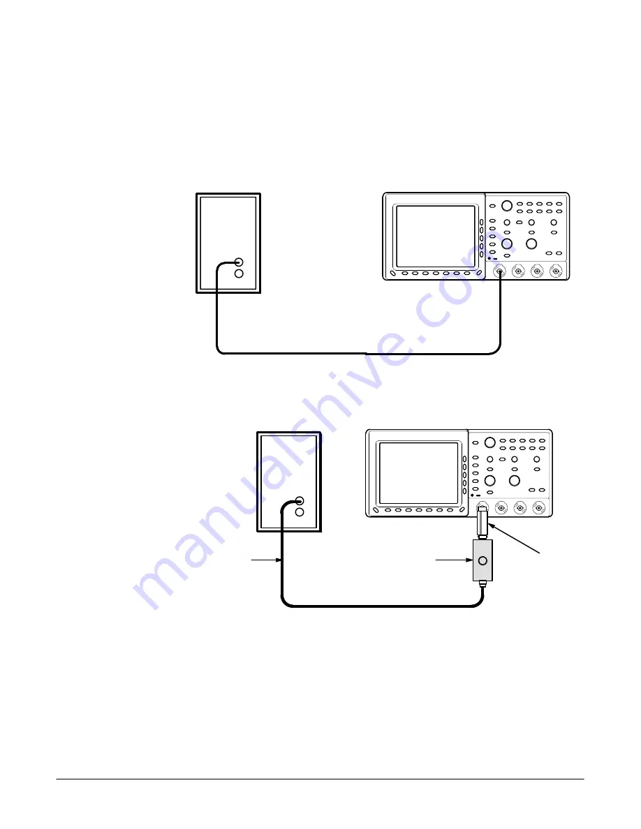
Figure 5-8: Initial Test Hookup (TDS 410 and TDS 420 Only)
Calibration
Generator
Tunnel Diode Pulser
10X attenuator
Precision Cable
Output
Figure 5-9: Initial Test Hookup (TDS 460 Only)
b.
Hook up test-signal source (TDS 410 and TDS 420 Only):
H
Connect the high-amplitude output of a calibration generator,
through a 50
W
precision cable to the CH 1 input (see Figure 5-8).
Summary of Contents for 410
Page 9: ...Contents x ...
Page 13: ...Contents xx ...
Page 19: ...Safety Summary xx ...
Page 25: ...Introduction x x ...
Page 26: ...Specifications ...
Page 47: ...Operating Information ...
Page 63: ...Operating Information Operating Information 2Ć16 ...
Page 64: ...Theory of Operation ...
Page 68: ...Circuit Description Theory of Operation 3Ć4 ...
Page 69: ...Performance Verification ...
Page 81: ...Brief Procedures Performance Verification 4Ć12 ...
Page 119: ...Performance Tests Performance Verification 4Ć50 ...
Page 120: ...Adjustment Procedures ...
Page 147: ...Maintenance ...
Page 151: ...Maintenance Information Maintenance 6Ć4 ...
Page 240: ...Options ...
Page 249: ...Electrical Parts List ...
Page 251: ...Replaceable Electrical Parts List Electrical Parts List 8Ć2 ...
Page 252: ...Diagrams ...
Page 258: ...Diagrams 9Ć6 ...
Page 259: ...Mechanical Parts List ...
Page 263: ...Mechanical Parts List 10Ć4 ...
Page 275: ...Mechanical Parts List 10Ć16 ...


