47
Step 1: Before Continuing Troubleshooting…
WARNING!
All electric power should be disconnected and you should have already made
sure that the compressor does not have a ground fault (see “Checking for a Ground Fault”
on pages 40-41).
You should have also checked the windings for continuity and proper
resistance (see “Checking for Continuity and Proper Resistance” on page 42), made sure
the system is getting proper voltage, and that the control, thermostat, and contactor are
working properly.
Step 2: Disconnect Fan Motor or Any Other Devices
If there is a fan motor or any other auxiliary device, open the circuit for the fan motor or any
other device.
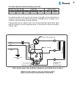
Step 3: Check Wired-in PTC Relay
Check the relay by measuring continuity between the pin holes where the R and S pins on
the compressor are inserted. If there is no continuity, the relay may be open. Wait 3 min-
utes, then check continuity again. If there is still no continuity, replace the relay.
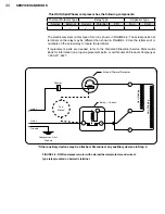
Step 4: Check External Thermal Protector
Check for continuity across the thermal protector (line 1 and compressor terminal con-
nection). If there is no continuity then the thermal protector may be tripped. Wait for the
protector to cool off and close. This may take more than an hour. Check continuity gain.
If there is no continuity, replace the protector.
Step 5: Continue Troubleshooting
If all above tests prove satisfactory and unit still fails to operate properly check for adequate
compressor pumping as outlined in the procedure on page 70.
Summary of Contents for AH5540E
Page 1: ...Hermetic Compressor Service Handbook Wholesale Distribution North America...
Page 2: ......
Page 3: ...Hermetic Compressor Service Handbook Ann Arbor MI 48108 REV 3 11...
Page 4: ......
Page 8: ......
Page 9: ...Chapter 1 General Service Safety Precautions...
Page 16: ......
Page 17: ...Chapter 2 Model and Application...
Page 22: ......
Page 23: ...Chapter 3 Compressor Motor and Component...
Page 36: ......
Page 37: ...Chapter 4 Servicing...
Page 38: ...30 SERVICE HANDBOOK...
Page 79: ...71...
Page 80: ......
Page 81: ...Chapter 5 Installation and Replacement...
Page 96: ......
Page 97: ...Liquid refrigerant migration to compressor FIGURE 6 1 Chapter 6 Operation...
Page 108: ......
Page 109: ...Appendix...
Page 113: ...105 Reciprocating Compressor FIGURE A 2 Internal view of typical air conditioning compressor...
Page 118: ...110 SERVICE HANDBOOK Notes...
Page 119: ......

