background image

Summary of Contents for AH5540E

Page 1: ...Hermetic Compressor Service Handbook Wholesale Distribution North America...

Page 2: ......

Page 3: ...Hermetic Compressor Service Handbook Ann Arbor MI 48108 REV 3 11...

Page 4: ......

Page 5: ...formation in this Service Handbook is generally limited to the compressor and to items and conditions affecting the installation operation and servicing of the compressor It is not designed to be a te...

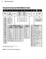
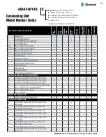
Page 6: ...itor Overheating 7 System Evacuation 7 Follow the Labels 8 Model and Application 9 Compressor Model Number Codes 10 Condensing Unit Model Number Codes 11 Serial Label Information 12 Basic Application...

Page 7: ...placing Compressors in Water Utilizing Systems Preventing Explosions 87 Operation 89 Control of Liquid Migration to the Compressor During Shutdown 90 Crankcase Heaters 93 Starting a System with Liquid...

Page 8: ......

Page 9: ...Chapter 1 General Service Safety Precautions...

Page 10: ...and Electrocution Precautions To reduce the risk of electrocution or serious burns or death from terminal venting with ignition Be alert for sounds of arcing sizzling sputtering or popping inside the...

Page 11: ...use extreme caution to avoid electric shock FIGURE 1 1 Compressor with 1 protective cover and 2 bale strap removed to show 3 hermetic terminal FIGURE 1 2 Close up view of hermetic terminal show ing in...

Page 12: ...bite cause a fire if a torch is used to disconnect tubing expose the service person to toxic gas To avoid serious injury or death be sure to remove and recover all refrigerant before removing the comp...

Page 13: ...system Do not operate the compressor without charge in the system Operating the compressor without a charge in the system can damage the hermetic terminal As always to avoid serious injury or death fr...

Page 14: ...xplosion of the compressor or other system components Service Procedures In light of the risk of explosion be especially alert for signs of water leaking into the refrig erant side of the system Whene...

Page 15: ...he heat exchanger The entire system must be replaced See Replacing a Single wall Water utilizing System on page 33 If you do not find any indication of a history of loss of charge without detection of...

Page 16: ......

Page 17: ...Chapter 2 Model and Application...

Page 18: ...nj 10 F High G Low Vapor Inj 10 F High In this example 4 total digits with the first two 40 or 4 000 BTU capacity Primary Refrigerants A R12 B R410A C R407C E R22 J R502 U R290 M R600a Y R134a Z R404A...

Page 19: ...ing Units HL Outdoor Condensing Unit with Options Celseon Air Cooled Units CB Std Unit W EC Fan Motor Sweat Conns Power Cord Receiver Tank CC Std Unit W EC Fan Motor Sweat Conns Power Cord Receiver Ta...

Page 20: ...The only source for complete compressor information is on the compressor serial label On earlier compressors the serial plate is usually spot welded on the upper housing of the compressor For current...

Page 21: ...e using R 404A in a compressor designed for R 134a can lead to higher operating pressures that can overload the bearings and overwork the motor Use of a refrigerant other than the serial label refrige...

Page 22: ......

Page 23: ...Chapter 3 Compressor Motor and Component...

Page 24: ...ral lel with each other and in series with the motor start winding see Figure 3 4 This motor has high starting torque runs efficiently and is used on many refrigeration and air condi tioning applicati...

Page 25: ...ting and operating characteristics and the field conditions that can affect it The following conditions affect PSC motor starting Low voltage Reduces motor start ing and running torque A 10 voltage dr...

Page 26: ...oo small will cause nuisance tripping see Fuse and Circuit Breaker Sizing on page 27 If the fuse or circuit breaker trips see Identifying Compressor Electrical Problems on pages 40 41 for electrical t...

Page 27: ...see Figure 3 8 reacts to excess temperature and or excess current draw by flexing downward and disconnecting the compressor from the power source Figures 3 9 and 3 10 show the installation of a therma...

Page 28: ...specific details consult an authorized wholesaler Originally used on some AN and SF models Employs use of solid state temperature sensors in motor windings and compressor discharge muffler Sensor resi...

Page 29: ...te starting device is placed in series with the start winding and normally has a very low resistance Upon startup as current starts to flow to the start winding the resistance rapidly rises to a very...

Page 30: ...potential relays with hermetic compressors A large number of these have been used on air conditioning applications but there are also many other applications Since there are many variations with regar...

Page 31: ...lay Code 128 12 2 13 3 5 C A POTENTIAL RELAY TYPE TYPE OF BRACKET CONTACT STRUCTURE TERMINALS TYPE AND LOCATION COIL GROUP CONTINUOUS VOLTAGE MOUNTING POSITION CALIBRATION HOT PICK UP VOLTS CUSTOMER S...

Page 32: ...lay from functioning Capacitor fail ure and or starting winding failure could result To eliminate this Tecumseh Products Company start capacitors are equipped with bleeder resistors wired across the c...

Page 33: ...amount and the limits are shown in Table 3 5 Remember the voltage rating of all capacitors must be the same or greater than the original rating If the voltage rating is not known use 370 volt capacit...

Page 34: ...ssor models have terminal pin identification embossed on the protective terminal cover While the protective terminal cover may identify the terminal pins it is primarily designed to reduce the risk of...

Page 35: ...cuit breaker used to protect against short circuit and or ground fault of a unit utilizing a hermetic compressor shall be no more than the sum of 225 of the compressor Rated Load Amps RLA as marked on...

Page 36: ......

Page 37: ...Chapter 4 Servicing...

Page 38: ...30 SERVICE HANDBOOK...

Page 39: ...ver reset a breaker or replace a fuse without first checking for a ground fault also known as a short circuit to ground Before Servicing Servicing Introduction to Servicing This chapter provides infor...

Page 40: ...refrig erant side of the system Whenever servicing or troubleshooting a water utilizing system always check to see if it has either a pressure relief valve or a high pressure cut out as previously de...

Page 41: ...replaced See Replacing a Single wall Water utilizing System below If water does not come out of the process valve there is still a possibility that some water has leaked into the refrigerant side of t...

Page 42: ...warranty see Is Your Compressor Eligible for Return Under Warranty on page 70 Table 4 1 Troubleshooting Chart Complaint Possible Causes Response Compressor will not start no hum System component not...

Page 43: ...40 41 Liquid refrigerant in compres sor Add crankcase heater and a suction line accumulator It is difficult to determine how liquid refrigerant got into the compressor A crankcase heater along with a...

Page 44: ...extra sources of current passing through thermal protector such as fan motors pumps Refer to the OEM service infor mation 2 See Identifying Compres sor Electrical Problems on pages 40 41 Low voltage...

Page 45: ...Water leak into refrigerant side of a water utilizing system 1 3 Refer to the OEM ser vice information 4 See Servicing or Troubleshooting Water Utilizing Systems Preventing Explosions on pages 32 33 A...

Page 46: ...o high System problems such as 1 Control setting too high 2 Expansion device restrict ed or too small 3 Cooling coils too small 4 Inadequate air circulation Refer to the OEM service infor mation Water...

Page 47: ...r or liquid shut off king valve partially closed Refer to the OEM service infor mation Water leak into refrigerant side of a water utilizing system System rattles or vibrates dur ing operation Loose p...

Page 48: ...alled terminal venting with ignition To reduce the risk of electrocution serious burns or death from terminal venting with igni tion Be alert for sounds of arcing sputtering or popping inside the comp...

Page 49: ...ad separately If a ground fault does not exist leave the power off and all external components discon nected from the terminal pins Check for continuity and proper resistance using the pro cedure on p...

Page 50: ...erminal pins Leg1 Leg2 Leg2 Leg3 and Leg1 Leg3 If there is no continuity replace the compressor See System Cleanup and Compressor Replacement After Compressor Failure on pages 83 86 Step Three Measure...

Page 51: ...for the compressor you are servicing For more information on Compressor motor types see Single phase Compressor Motor Types on pages 16 17 Thermal protectors see Hermetic Compressor Thermal Protector...

Page 52: ...he actual relay to locate the terminals If replacement parts are needed refer to the Tecumseh Electrical Service Parts Guide Book for information on proper replacement parts or call Tecumseh Products...

Page 53: ...inal con nection If there is no continuity then the thermal protector may be tripped Wait for the protector to cool off and close This may take more than an hour Check continuity gain If there is no c...

Page 54: ...relay to locate the terminals If replacement parts are needed refer to the Tecumseh Electrical Service Parts Guide Book for information on proper replacement parts or call Tecumseh Products Company at...

Page 55: ...device Step 3 Check Wired in PTC Relay Check the relay by measuring continuity between the pin holes where the R and S pins on the compressor are inserted If there is no continuity the relay may be op...

Page 56: ...s on the actual relay to locate the terminals If replacement parts are needed refer to the Tecumseh Electrical Service Parts Guide Book for information on proper replacement parts or call Tecumseh Pro...

Page 57: ...thermal protector line 1 and compressor terminal con nection If there is no continuity then the thermal protector may be tripped Wait for the protector to cool off and close This may take more than a...

Page 58: ...o locate the terminals If replacement parts are needed refer to the Tecumseh Electrical Service Parts Guide Book for information on proper replacement parts or call Tecumseh Products Company at 1 800...

Page 59: ...ntacts are closed when they should be open Replace the current relay Relay terminals 2 and M If there is no continuity replace the current relay Step 5 Check Start Capacitor CAUTION using a 20 000 ohm...

Page 60: ...or low pressure cut out For more information on troubleshooting the system components refer to the OEM service information Step 6 Replace Current Relay If all above tests prove satisfactory there is n...

Page 61: ...t parts are needed refer to the Tecumseh Electrical Service Parts Guide Book for information on proper replacement parts or call Tecumseh Products Company at 1 800 211 3427 Relay Potential Compressor...

Page 62: ...the protector Step 4 Check Protector Wiring Confirm that there is continuity between The power input terminal on the thermal protector and 5 on relay The protector common lead wire and C Step 5 Check...

Page 63: ...relay Prolonged operation on start cycle due to low voltage Determine if the line voltage is too low less than 90 of rated voltage Prolonged operation on start cycle due to incorrect relay Replace wi...

Page 64: ...parts are needed refer to the Tecumseh Electrical Service Parts Guide Book for information on proper replacement parts or call Tecumseh Products Company at 1 800 211 3427 Rela y Potential Compressor U...

Page 65: ...r high or low pressure cut out For more information on troubleshooting the thermal protector see Step 5 For troubleshooting the system components refer to the OEM service information Vibration due to...

Page 66: ...Prolonged operation on start cycle due to starting load too high Refer to the OEM service information to use pump down arrangement if necessary Excessive short cycling Short cycling can be caused by p...

Page 67: ...Company at 1 800 211 3427 FIGURE 4 9 CSR compressor motor type with internal thermal protector with start winding protection potential relay and run and start capacitors FIGURE 4 8 CSR compressor mot...

Page 68: ...the system Use a capacitance meter to check capacitor Capaci tance should be 10 of the marked capacitor value As an alternative check the run capacitor by measuring continuity across the capacitor te...

Page 69: ...perly include Use of incorrect start capacitor Replace with proper start capacitor The relay contacts are not working properly Replace the relay Prolonged operation on start cycle due to low voltage D...

Page 70: ...the Tecumseh Electrical Service Parts Guide Book for information on proper replacement parts or call Tecumseh Products Company at 1 800 211 3427 FIGURE 4 10 PSC compressor motor with external thermal...

Page 71: ...ng devices and risk of electric shock Disconnect the run capacitor from the system Use a capacitance meter to check capacitor Capacitance should be 10 of the marked capacitor value As an alternative c...

Page 72: ...eeded refer to the Tecumseh Electrical Service Parts Guide Book for information on proper replacement parts or call Tecumseh Products Company at 1 800 211 3427 FIGURE 4 12 PSC compressor motor type wi...

Page 73: ...is no continuity replace the compressor Step 3 Check Run Capacitor CAUTION using a 20 000 ohm resistor discharge the capacitor before removing it from the system to avoid damage to measuring devices...

Page 74: ...he terminals If replacement parts are needed refer to the Tecumseh Electrical Service Parts Guide Book for information on proper replacement parts or call Tecumseh Products Company at 1 800 211 3427 O...

Page 75: ...If there is continuity then the run capacitor is shorted and needs to be replaced Rx100 000 scale If there is no needle deflection on an analog meter or if a digital meter indicates infinite resistan...

Page 76: ...cate the terminals If replacement parts are needed refer to the Tecumseh Electrical Service Parts Guide Book for information on proper replacement parts or call Tecumseh Products Company at 1 800 211...

Page 77: ...eplaced Rx100 000 scale If there is no needle deflection on an analog meter or if a digital meter indicates infinite resistance then the run capacitor is open and needs to be replaced Possible reasons...

Page 78: ...essor does not pump adequately it must be replaced with no further testing Is Your Compressor Eligible for Return Under Warranty Authorized Tecumseh wholesalers are asked to test every in warranty com...

Page 79: ...71...

Page 80: ......

Page 81: ...Chapter 5 Installation and Replacement...

Page 82: ...or the suction connection may be used for processing the system Identification of compressor connections can usually be accomplished without difficulty however occasionally some question arises concer...

Page 83: ...75 FIGURE 5 1 cont Standard discharge tubing arrangements AK Discharge Tube Discharge Tube Discharge Tube Discharge Tube Discharge Tube Discharge Tube AJ AH AV AZ AN AG AB RK RG...

Page 84: ...e case of a flooded type evaporator bottom feed top suction header large inter nal volume low refrigerant oil velocities it is necessary to maintain a liquid spillover into the suction line so as to r...

Page 85: ...16 3 8 3 8 1 2 1 2 3 8 12 000 1 2 1 2 5 8 5 8 1 2 1 4 5 16 5 16 3 8 5 16 3 8 1 2 1 2 1 2 3 8 18 000 1 2 5 8 5 8 3 4 5 8 1 4 5 16 3 8 3 8 3 8 3 8 1 2 1 2 5 8 3 8 24 000 5 8 5 8 3 4 7 8 3 4 5 16 3 8 3 8...

Page 86: ...1 8 5 16 3 8 1 2 1 2 1 2 1 2 5 8 3 4 3 4 5 8 48 000 7 8 1 1 8 1 1 8 1 3 8 1 1 8 3 8 1 2 1 2 5 8 5 8 5 8 5 8 3 4 7 8 3 4 Table 5 3 R 134a Refrigerant Line Sizes 45 F Evap Temp 65 F Suction Vapor Temp 1...

Page 87: ...000 5 8 3 4 7 8 1 1 8 7 8 1 4 5 16 3 8 3 8 5 16 3 8 1 2 1 2 1 2 3 8 18 000 3 4 7 8 1 1 8 1 1 8 7 8 5 16 3 8 3 8 1 2 3 8 3 8 1 2 5 8 5 8 1 2 Table 5 5 R134a Refrigerant Line Sizes 10 F Evap Temp 40 F...

Page 88: ...6 5 16 3 8 5 16 5 16 3 8 3 8 1 2 5 16 10 000 1 2 1 2 5 8 5 8 1 2 1 4 5 16 5 16 3 8 3 8 5 16 3 8 1 2 1 2 3 8 12 000 1 2 1 2 5 8 3 4 1 2 1 4 5 16 3 8 3 8 3 8 3 8 1 2 1 2 1 2 3 8 18 000 1 2 5 8 3 4 3 4 5...

Page 89: ...2 5 8 5 8 1 2 5 8 3 4 3 4 5 8 48 000 7 8 1 1 8 1 1 8 1 3 8 1 1 8 1 2 1 2 5 8 5 8 3 4 5 8 3 4 3 4 7 8 3 4 60 000 1 1 8 1 1 8 1 3 8 1 3 8 1 3 8 1 2 1 2 5 8 5 8 7 8 5 8 3 4 7 8 1 1 8 7 8 Table 5 8 R 404A...

Page 90: ...rn gas temperatures to the compressor 2 To prevent oxidation and scale forming inside the tubes it is good practice to flow dry nitrogen through the tubing during the soldering operations A light flow...

Page 91: ...upper housing sweating indicating that liquid refrigerant is reaching the compressor Is the return gas temperature at the compressor within proper limits for the application i e not too low to cause f...

Page 92: ...rier immediately upstream of the compressor The filter drier when permanently installed in a clean system or as initially installed in a dirty system must have a pressure drop not more than listed in...

Page 93: ...e Drop After the system has been operating for an hour or so measure the pressure drop across the suction line filter drier In the case of Compressor Housing Contamination little change should be note...

Page 94: ...l may be slowly transferred to the beaker of the acid test kit as available from several manufac turers A reading of less than 0 05 acid number is an indication that the system is free of acid A readi...

Page 95: ...ystems that have single wall heat exchangers may present a risk of explosion Such systems may include water source heat pump air conditioning systems and water cooling systems such as icemakers water...

Page 96: ......

Page 97: ...Liquid refrigerant migration to compressor FIGURE 6 1 Chapter 6 Operation...

Page 98: ...boratories of Tecumseh Products Com pany A five ton split air conditioning system was used with a four inch sign glass installed in the compressor housing The condensing unit and evaporator sections w...

Page 99: ...econds after start up violent foaming action fill sight glass as re frigerant boils away taking oil charge with it FIGURE 6 3 More than 60 seconds after start up oil level is well below normal operati...

Page 100: ...odback under certain conditions while operating This condition can be controlled by the application of a suction line accumulator Crankcase heat does nothing to prevent liquid floodback and an accumul...

Page 101: ...F The immersion type heater is factory assembled and is presently used with AB AW AG AV and AN compressors It is self regulating and energy efficient In the run capacitance off cycle heat method used...

Page 102: ...ne to two seconds then wait 1 to 2 minutes After 3 or 4 jogs apply power continuously WARNING Jogging a compressor that has an electrical problem can increase the likelihood of terminal venting To red...

Page 103: ...in an accumulation of the refrigerant under the oil see Figure 6 10 Thus when the compressor is started the first liquid to be pumped to the bearings will probably be refrigerant not oil Even if this...

Page 104: ...6 10 Five seconds after start up violent foaming action fills sight glass as refrigerant boils away taking the oil charge with it FIGURE 6 11 More than 60 seconds after start up oil level is well belo...

Page 105: ...mpressor during periods of shutdown This condition can be controlled by the application of a crankcase heater A suction line accumulator does nothing to prevent liquid migration and a crankcase heater...

Page 106: ...nts such as evaporator temperature and capacity in tons of refrigeration These factors were considered in the design and testing of the accumulator On older systems if the system refrigerant charge is...

Page 107: ...in refrigeration systems The IPR valve may also open to relieve hydraulic pres sures in the event of slugging This is apt to occur on startup if refrigerant has been allowed to mi grate to the compre...

Page 108: ......

Page 109: ...Appendix...

Page 110: ...trolled by the pressure differential across the expansion device or in the case of a thermostatic expansion valve TEV by the amount of superheat of the suction gas Thus the TEV shown requires its sens...

Page 111: ...ompressor Discharge Pressure Cutout Crankcase Heater LO HI Evaporator Fan Low Pressure Side Evaporator Accumulator Thermostatic Expansion Valve or Capillary Tube TEV Sensin Bulb Heat Exchanger Receive...

Page 112: ...s Refrigerant gas surrounds the compressor crankcase and motor as it is drawn through the compressor housing and into the cylinder s through the suction muffler and suction valves As the gas is pressu...

Page 113: ...105 Reciprocating Compressor FIGURE A 2 Internal view of typical air conditioning compressor...

Page 114: ...heat exchange length Capillary Tube Length OD Evaporator Temperature F Refrigerant Btu h per circuit 10 20 45 22 500 19 ft 0 026 18 ft 0 026 17 ft 0 026 750 12 ft 0 028 11 ft 0 028 10 ft 0 028 1 000 1...

Page 115: ...e same capacity as 16 ft of 0 031 capillary 404A 507 500 17 ft 0 031 18 ft 0 031 19 ft 0 031 750 16 ft 0 036 17 ft 0 036 18 ft 0 036 1 000 9 ft 0 036 9 ft 0 036 10 ft 0 036 1 250 12 ft 0 042 13 ft 0 0...

Page 116: ...be taken not to exceed the oil charge amounts specified See Refrigerant Line Sizes on pages 76 81 If the correct oil charge is in doubt please obtain assistance from your Tecumseh Technical Service R...

Page 117: ...5 Lubrax BR 069C EX 4 4 Lubrax ALP 415 LCR 4 4 Naphthenic Paraffinic Sonneborn Witco LP 200 3 3 3 3 Penreco Sontex 200LT A LT 3 3 3 3 Paraffinic Total Oil Company 68CST 6 Petrobas CP 68 RAD 6 Polyol E...

Page 118: ...110 SERVICE HANDBOOK Notes...

Page 119: ......

Page 120: ...of arcing sizzling sputtering or popping inside the compressor IMMEDIATELY GET AWAY if you hear these sounds Disconnect ALL electrical power before removing the protective thermal cover Never energiz...

Reviews: