74
SERVICE HANDBOOK
Compressor Tube Connections
Tecumseh Products Company supplies compressors to hundreds of manufacturers requiring dif-
ferent tubing sizes and arrangements. Because of this the same compressor model may be found
in the field in many suction and discharge tube variations, each depending upon the specific ap-
plication in which it is installed.
Suction connections can usually be identified as the largest diameter stub tube in the housing. If
2 stubs have the same outside diameter (OD), then the one with the heavier wall will be the suction
connection. If both of the largest stub tubes are the same OD and wall thickness, then either can
be used as the suction connection. Whenever possible, suction connections should be kept away
from the hermetic terminal area so that condensation will not drip on hermetic terminals, causing
corrosion.
The stub tube, not chosen for the suction connection, may be used for processing the system.
Identification of compressor connections can usually be accomplished without difficulty; however,
occasionally some question arises concerning oil cooler tubes and process tubes.
Oil cooler tubes are found only in low temperature refrigeration models. These tubes connect to
a coil or hairpin bend within the compressor oil sump. This coil or hairpin bend is not open inside
the compressor and its only function is to cool the compressor sump oil. The oil cooler tubes are
most generally connected to a separated tubing circuit in the air-cooled condenser.
Process tubes are installed in compressor housings during manufacture as an aid in factory de-
hydration and charging.
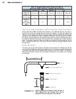
Standard discharge tubing arrangements for Tecumseh hermetic compressors are outlined below.
Discharge tubes are generally in the same position within any model family. Suction and process
tube positions may vary substantially.
On some AE refrigeration
models, the terminal cover
faces the other way.
FIGURE 5-1: Standard discharge tubing arrangements.
Summary of Contents for AH5540E
Page 1: ...Hermetic Compressor Service Handbook Wholesale Distribution North America...
Page 2: ......
Page 3: ...Hermetic Compressor Service Handbook Ann Arbor MI 48108 REV 3 11...
Page 4: ......
Page 8: ......
Page 9: ...Chapter 1 General Service Safety Precautions...
Page 16: ......
Page 17: ...Chapter 2 Model and Application...
Page 22: ......
Page 23: ...Chapter 3 Compressor Motor and Component...
Page 36: ......
Page 37: ...Chapter 4 Servicing...
Page 38: ...30 SERVICE HANDBOOK...
Page 79: ...71...
Page 80: ......
Page 81: ...Chapter 5 Installation and Replacement...
Page 96: ......
Page 97: ...Liquid refrigerant migration to compressor FIGURE 6 1 Chapter 6 Operation...
Page 108: ......
Page 109: ...Appendix...
Page 113: ...105 Reciprocating Compressor FIGURE A 2 Internal view of typical air conditioning compressor...
Page 118: ...110 SERVICE HANDBOOK Notes...
Page 119: ......


