VARIO : Service & maintenance manual- rev. 4.2
Page 7.14
7.2.2.6.
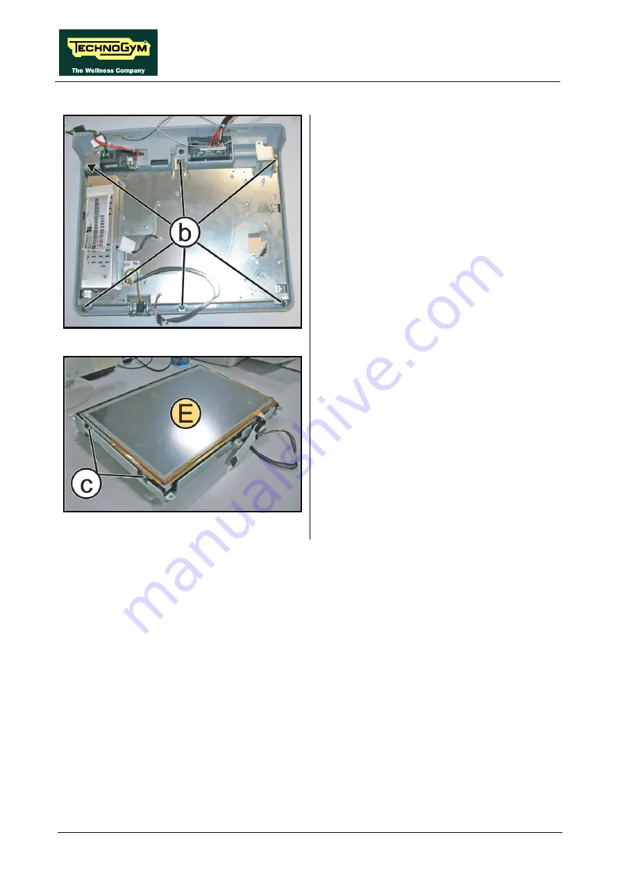
LCD (E) + Touch Screen
Figure 7.2-16
Carry out the procedure described in paragraph:
7.2.2.5 “CPU board (D)”.
1.
Back off the 6 screws
(b)
using a medium
Phillips Screwdriver.
2.
Remove the LCD Inverter as described in the
paragraph: 7.2.2.4 “LCD Inverter (C)”.
3.
Remove the LCD group completely.
Figure 7.2-17
4.
Carefully overturn the LCD group.
5.
Back off the 2 screws
(c)
on the both side,
using a medium Phillips Screwdriver.
6.
Remove the LCD
(E)
from the support plate.
To reassemble the LCD and the Touch Screen,
follows the above steps in the reverse order.
Summary of Contents for Vario Excite + 500
Page 1: ...V VA AR RI IO O E X C I T E REV 4 2...
Page 2: ......
Page 4: ......
Page 10: ...VARIO Excite Service maintenance manual rev 4 2 Page vi Page intentionally left blank...
Page 58: ...VARIO Excite Service maintenance manual rev 4 2 Page 5 6 Page intentionally left blank...
Page 170: ...VARIO Excite Service maintenance manual rev 4 2 Page 7 70 Page intentionally left blank...
Page 206: ...VARIO Excite Service maintenance manual rev 4 2 Page 9 26 Page intentionally left blank...
Page 208: ...VARIO Excite Service maintenance manual rev 4 2 Page 10 2 Page intentionally left blank...
Page 219: ......


