SYNCHRO EXCITE Class & Trend: Service & maintenance manual - rev. 2.0
Pagina 7.34
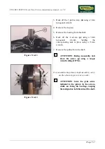
Figure 7.14-4
To disassemble the shaft you need to have the kit
R0003810AA.
1.
Insert the special tool
x
on the shaft
2.
Lock down the screw
y
on the shaft using 13
mm wrench until the pressure is removed
from the snap ring.
3.
Using the special pliers, remove the snap
ring from its seat, sliding it upward.
4.
Back off the screw and remove part b.
5.
Pull the components out of the assembly.
Figure 7.14-1
To reassemble the shaft group, look at the
picture at the side and proceed as follows:
1.
Place all the components on the shaft,
respecting the correct order and the direction
of insertion, as shown on the side.
2.
Place the spacer, the seeger and the seeger’s
covering piece.
3.
Insert the special tool
(x)
on the shaft,
locking down the screw
(y)
until the snap
ring seat is completely visible (
as above
).
4.
Push the snap ring into its seat with the help
of a screwdriver.
It continues at page 7.36 of this procedure.
Summary of Contents for Synchro Excite 500
Page 1: ...SERVICE MAINTENANCE MANUAL REV 2 0 ...
Page 2: ......
Page 4: ......
Page 48: ...SYNCHRO EXCITE Class Trend Service maintenance manual rev 2 0 Pagina 4 6 LIBYA DVB T ...
Page 50: ......
Page 201: ......

