


SYNCHRO EXCITE Class & Trend: Service & maintenance manual - rev. 2.0
Page 6.37
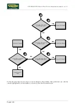
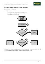
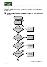
Is the supply voltage correct at
the output of the display board?
Replace cable ELT-19
Replace the display board
5
YES
NO
A
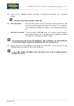
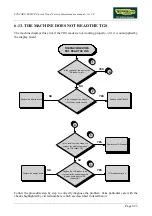
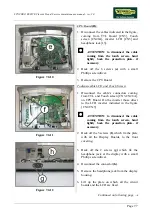
Follow the procedure step by step to correctly diagnose the problem. Take particular care with the
checks highlighted by circled numbers, which are described in detail below:
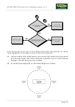
(1)
Check the earth connection of the machine using a tester to measure the resistance between
the ground pin on the power supply cable and the ground node to which the receiver is
connected inside the display. The value must be less than 1
Ω
(Ohm).
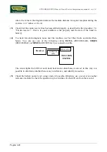
(2)
Check the connections, referring to paragraph 2.7. “Wiring diagrams”.
(3)
Place the tester probes across pins 2 and 1 of connector J3 on the HS interface board. The
measured value should be +5 Vdc.
(4)
As for point (2) but on patch connector 6.
(5)
As for step (2) but across pins 1 and 6 of connector CN4 on the display board.
Summary of Contents for Synchro Excite 500
Page 1: ...SERVICE MAINTENANCE MANUAL REV 2 0 ...
Page 2: ......
Page 4: ......
Page 48: ...SYNCHRO EXCITE Class Trend Service maintenance manual rev 2 0 Pagina 4 6 LIBYA DVB T ...
Page 50: ......
Page 201: ......


