SYNCHRO EXCITE Class & Trend: Service & maintenance manual - rev. 2.0
Pagina 3.4
3.1.3.
W
ELLNESS
TV
D
ISPLAY BOARDS
–D
IGITAL
TV
(700WTV)
3.1.3.1.
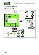
CPU board
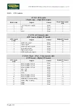
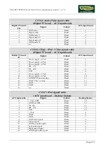
The board is called “Unified Board”, it is the circuit board which incorporates the CPU, its control
logic, the FLASH EPROM containing the operating program of the machine.
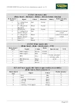
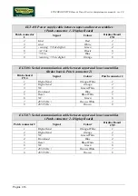
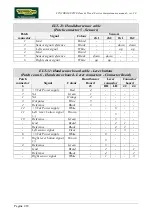
It is the circuit board which acts as the interconnection hub for all the components of the display
and serves as the point of connection with the digital TV Board and the Brake Board.
The main functions of the board are:
¾
Manages and process the signal from:
LCD;
Inverter for LCD;
Touch screen;
Headphone jack;
AUX input Board;
HS/HR receiver;
Touch sensors;
TGS reader (if present);
iPod docking station (if present).
¾
Distributes the voltages received from the Brake Board to the display;
¾
Exchanges, via the RS-485 serial link to the Brake Board, the commands for controlling the brake;
¾
Manages the display of images on the LCD.
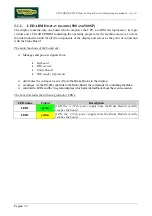
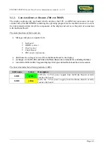
The board includes the following indicator LED:
LED name
Colour
Description
D41
green
if ON the +12 Vdc supply from the Brake Board correctly
reaches the CPU board.
and a faston:
Nome Descrizione
J2
denotes a ground node on the circuit
board.
3.1.3.2.
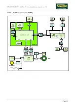
Digital TV board
It’s the circuit board which contains the decoder and all the components needed to receive and
manage the aerial antenna signal.
Directly to this board it is connected the antenna cable. Here it’s signal is amplified, divided
between the video and audio signal, codified by the decoder and managed by the tuner which
allows to tune the TV and radio channels.
Due to its positioning on the rear display support, just over the AUX input board, it is also used as a
“bridge” for the signals between AUX input board and iPod docking station, and CPU board.
Summary of Contents for Synchro Excite 500
Page 1: ...SERVICE MAINTENANCE MANUAL REV 2 0 ...
Page 2: ......
Page 4: ......
Page 48: ...SYNCHRO EXCITE Class Trend Service maintenance manual rev 2 0 Pagina 4 6 LIBYA DVB T ...
Page 50: ......
Page 201: ......

