SYNCHRO EXCITE Class & Trend: Service & maintenance manual - rev. 2.0
Pagina 7.40
7.17.
PLATFORMS WITH CSAFE BORAD, CONNECTORS,
POWER ENTRY MODULE AND WHEELS DISASSEMBLY
Figure 7.17-1
Carry out the operations described in paragraph
7.7. “Guards” for removing the front guards.
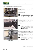
1.
To disassemble the plastic covers from the
platforms, turn the machine over on one side.
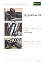
2.
Back off the screws
(a)
for the front covers
and/or the screws
(b)
for the rear covers.
Figure 7.17-2
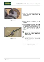
Underneath the front platforms (at left in the
figure) there are housings for:
•
Power entry module (500, 700 and
700WTV) or battery charger socket
(500SP and 700SP).
•
connector of the cable leading to the
CSafe board
At this point it is possible to:
1.
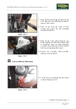
Back off the two screws
(c)
using a 4mm
hexagonal wrench, and remove the power
entry module.
2.
Unplug connector
(b)
of the cable leading up
to the CSafe board.
Continued on following page
→
Summary of Contents for Synchro Excite 500
Page 1: ...SERVICE MAINTENANCE MANUAL REV 2 0 ...
Page 2: ......
Page 4: ......
Page 48: ...SYNCHRO EXCITE Class Trend Service maintenance manual rev 2 0 Pagina 4 6 LIBYA DVB T ...
Page 50: ......
Page 201: ......

