


SYNCHRO EXCITE Class & Trend: Service & maintenance manual - rev. 2.0
Page 3.3
3.1.2.
L
ED
A
RM
D
ISPLAY
B
OARDS
(700
AND
700SP)
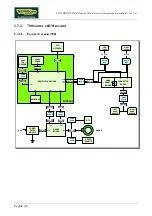
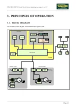
The display contains only one board which comprises the CPU, an ARM microprocessor, its logic
circuits and a FLASH EPROM containing the operating program for the machine moreover, acts as
the interconnection hub for all the components of the display and serves as the point of connection
with the Brake Board.
The main functions of the board are:
¾
Manages and process signals from:
Keyboard;
HS/HR receiver;
Touch sensor
CSafe Board;
TGS reader (if present).
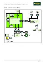
¾
distributes the voltages received from the Brake Board to the display;
¾
exchanges, via the RS-485 serial link to the Brake Board, the commands for controlling the brake;
¾
controls the LEDs and the 7-segment displays which provide feedback about the exercise session.
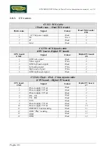
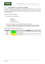
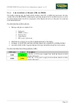
The board includes the following indicator LEDs:
LED name
Colour
Description
LED1
green
if ON the +12 Vdc power supply from the Brake Board correctly
reaches the board.
LED2
yellow
if ON the +5 Vdc power supply from the Brake Board correctly
reaches the board.
Summary of Contents for Synchro Excite 500
Page 1: ...SERVICE MAINTENANCE MANUAL REV 2 0 ...
Page 2: ......
Page 4: ......
Page 48: ...SYNCHRO EXCITE Class Trend Service maintenance manual rev 2 0 Pagina 4 6 LIBYA DVB T ...
Page 50: ......
Page 201: ......