SYNCHRO EXCITE Class & Trend: Service & maintenance manual - rev. 2.0
Pagina 2.16
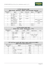
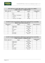
ELT-05: Power supply cable between upper and lower assemblies
(Patch connector 1 - Display Board)
Patch connector
1
Signal
Colour
Display Board
CN1
2 Gnd
Red
2
3 Gnd
White
3
4
- s5 Vdc digital
Green
4
6 +12
Vdc
Black
6
7 +5
Vdc
Blue
7
8
+s5 Vdc digital
Orange
8
ELT-06: Serial communication cable between upper and lower assemblies
(Brake board - Patch connector 2)
Brake board
CN4
Signal
Colour
Patch connector 2
1 Digital
Gnd
Orange-White
1
2 Digital
Gnd
Orange
2
3 NC
Green-White
3
4 Download
Blue
4
5 Reset
Blue-White
5
6 NC
Green
6
7
485 Tx/Rx +
Brown-White
7
8
485 Tx/Rx -
Brown
8
ELT-07: Serial communication cable between upper and lower assemblies
(Patch connector 2 - Display Board)
Patch connector 2
Signal
Colour
Display Board
CN9
1 Digital
Gnd
Orange-White
1
2 Digital
Gnd
Orange
2
3 NC
Green-White
3
4 Download
Blue
4
5 Reset
Blue-White
5
6 NC
Green
6
7
485 Tx/Rx +
Brown-White
7
8
485 Tx/Rx -
Brown
8
Summary of Contents for Synchro Excite 500
Page 1: ...SERVICE MAINTENANCE MANUAL REV 2 0 ...
Page 2: ......
Page 4: ......
Page 48: ...SYNCHRO EXCITE Class Trend Service maintenance manual rev 2 0 Pagina 4 6 LIBYA DVB T ...
Page 50: ......
Page 201: ......

