40
SAS UG 202205-01
SAFETY ARM SYSTEM INSTALLATION (CONTINUED)
INSTALLING THE STANDARD SURFACE BASE ONTO THE SAFETY ARM SYSTEM UPPER PLATE (CONTI-
NUED)
NOTE:
You will use only four (4) holes on the upper plate.
1.
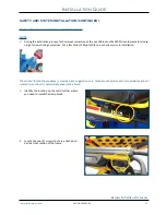
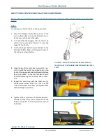
Place the Standard Surface Base on top of the
arm’s surface plate and use the hardware provi
-
ded to secure the base to the plate.
2.
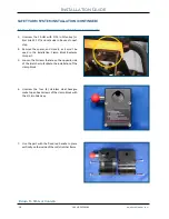
The round headed hexagon nuts (2) should be
placed on the same side of the arm to cover the
longer of the 4 bolts.
3.
Use the (2) longer bolts to secure the back of the
Standard Surface Base on the opposite side of
the red quick release button.
4.
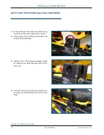
Align the two (2) stainless steel screws 10-32 in x
1-3/4 in with the two (2) pre-drilled holes in the
back of the upper plate and the Standard Surface
Base. Use Loctite™ on the four (4) bolts to avoid
potential loosening of the screws, due to vibra
-
tion.
5.
Repeat the same step with the other two (2)
stainless steel screws 10-32 in x 1-1/4 in at the
front or the middle of the base, and tighten them
with the Philips screwdriver.
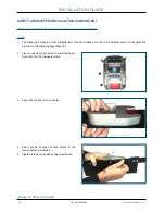
6. Tighten all four (4) screws of the Standard Sur
-
face Base at the front, and at the back with the
Philips screwdriver and the mechanical wrench
SAE 3/8 in.
FIGURE 17. PATIENT RIGHT SAFETY ARM SYSTEM INS
-
TALLATION OF THE STANDARD SURFACE BASE ON UPPER
PLATE
Installation Guide
4


