


TCF Termoventilatori Condizionatori Felsinea Srl
40057 Cadriano di Granarolo Emilia (Bologna), via Giuseppe di Vittorio 5
www.tcf.it
6
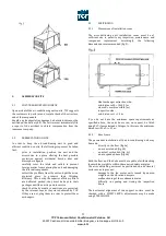
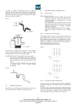
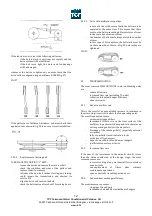
In order to prevent overflowing from the condensate
collection tank and consequent flooding of the machine and
the room it is installed in, the siphon must be fitted with a
DRAIN VALVE to permit the removal of impurities which may
deposit on the bottom (fig. 13).
FIG. 13
In order not to undermine the operation of the drainage
system, pressurised siphons and siphons operating under
suction pressure must not be connected together.
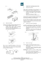
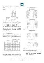
The WASTE PIPE (fig. 14) leading to the drainage network:
-
must not be connected directly to the siphon in
order to absorb air or waste backflow and to permit
direct visual control of the correct outflow of waste
water
-
must have a diameter larger than the drain pipe and
a minimum angle of 2% to ensure proper
functioning.
FIG. 14
4.4
FILTRATING SECTIONS
Check the correct installation of the prefilters located in the
relevant counterframes with safety springs or guides.
4.5
FAN-MOTOR UNITS (3-PHASES) series T
4.5.1
Electric motors
Before starting up the unit:
-
inspect the motor CONTROL BOARD and check that
the motor protection devices are sized for the
maximum amperage, corresponding to the rated
value on the plate.
-
The TERMISTORS, if present, must not be connected
to the power supply line of the electric motors since
otherwise they would be damaged irreparably
(operating voltage 1V)
-
Check that the MAINS SUPPLY VOLTAGE is suited to
that of the motors as indicated on the relevant
plates
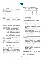
4.5.1.1
Connection for direct starting
The simplest electric motor start-up system is obtained by
connecting the motor directly to the supply line. However,
this method has limitations due to the high start-up current
(pick-up); this type of start-up is recommended for power
ratings up to 5,5kW for which TCF installs, as standard, 4-
poles 220/380 V three-phase motors.
The wiring diagrams are shown in fig. 15.
FIG. 15
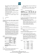
4.5.1.2
Connection with star-delta starting
If the motor start-up current exceeds the value permitted by
the power supply, you may decide to choose for delta-star
starting.
For this purpose TCF installs dual voltage 400/690V motors
on its air-conditioning units starting from an output of 7,5kW,
thus allowing the motor to operate normally at 400V (delta
connection) and to start-up at 690V (star connection).


