


TCF Termoventilatori Condizionatori Felsinea Srl
40057 Cadriano di Granarolo Emilia (Bologna), via Giuseppe di Vittorio 5
www.tcf.it
11
-
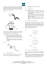
make sure that you have enough room for the
removal and temporary accommodation of the heat
exchanger
-
consider that an ordinary Cu/Al coil has a mass of
approximately 10 kg/m2 of frontal area per row;
therefore, prepare supports if necessary
-
completely drain the heat exchanger
-
remove the unit panel covering the hydraulic
connections and the panel through which the
exchanger will be removed
-
release the heat exchanger by undoing the relevant
clamps and extract it
-
on completion of the maintenance operations,
restore the ideal operating conditions of the
exchanger;
5.4
FAN SECTION
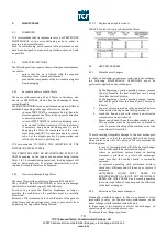
5.4.1
Fan
In order to keep the fan in perfect working order, WE
RECOMMEND YOU TO CHECK THE FOLLOWING AT LEAST
ONCE A MONTH:
-
The cleanliness of the shell and wheel; remove any
deposits
-
Damage and corrosion to the fan components; in
case remedy with zinc-powder paint
-
The tightness of the parts comprising the fan section
-
Seal of the vibration-damping joint fitted to the fan
supply mouth
-
Cleaning and lubrication of any DAPO control air
locks. Lubrication of this part must be performed
every six months
-
Absence of abnormal noises due to deterioration of
the bearings. If necessary, replace them. The fans
mounted on the TCF units are fitted wither with
oilless bearings (design life 2000 hours) or pedestal
bearings, depending on the operating conditions.
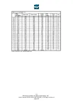
The pedestal bearings require periodic lubrication.
THE LUBRICATION INTERVALS show in table 3 are
subject to the environmental conditions and the
maximum temperature range during operation.
TABLE 3.
Lubrication of fan support bearings
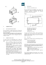
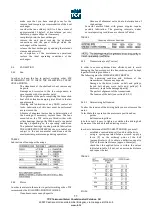
5.4.2
Motor
In order to maintain the motor in perfect working order, TCF
recommends the FOLLOWING MONTHLY CHECKS:
-
Cleanliness: remove any deposits
-
Absence of abnormal noise due to deterioration of
the bearings
Powerful motors fitted with grease nipples require
periodic lubrication. The greasing intervals, under
normal operating conditions, are shown in Table 4.
TABLE 4
Greasing of motor bearings
5.4.3
Transmission (only T series)
In order to ensure optimum drive efficiency and to avoid
damaging the fan motor unit, the transmission must be kept
in perfect working conditions.
The following must be CHECKED EVERY MONTH:
-
The operating condition and dirtiness of the
transmission; remove any deposits
-
Damage to the drive (cracks on belt and pulleys,
frayed belt edges, worn belts and pulleys). If
necessary, replace the damaged part(s)
-
The perfect alignment of the transmission
-
The tension of the belt (see section 5.4.3.1)
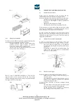
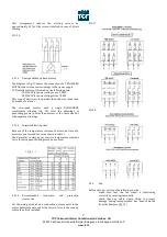
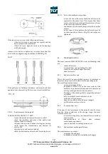
5.4.3.1
Determining belt tension
To alter the tension of the driving belts you must remove the
motor.
To facilitate this operation the motors are positioned on:
-
guides
-
belt-tensioning slides
in both cases it is easy to tighten or slacken the driving belt
by means of the lock nuts and adjusting screws.
In order to determine DRIVING BELT TENSION, you must:
-
establish a centre distance (I) and block the drive
-
using a spring-operated torque wrench, apply a
force (P) on the midway point of the belt
(perpendicular to it) to obtain a deflection equal to
1/64 of the centre distance (approx. 16mm/m)
-
check that the applied force is within the values
indicated in table 5, if not, set a new centre distance
and repeat the test
TABLE 5
FIG. 26