


TCF Termoventilatori Condizionatori Felsinea Srl
40057 Cadriano di Granarolo Emilia (Bologna), via Giuseppe di Vittorio 5
www.tcf.it
3
3.
ASSEMBLY ON SITE
3.1
POST-TRANSPORTATION CHECK
Upon arrival of the air-conditioning unit on site, TCF suggests
the customers to perform an accurate check of the structure
and of the components.
Should any transportation damage be detected, this must be
notified on the delivery bill. The carrier must immediately file
a report of the accident to obtain compensation from the
insurance company.
3.2
PRESERVATION ON SITE
In order to keep the air-conditioning unit in good and
efficient condition on site, the following steps must be taken
first:
-
prior to installation, position the unit and the
accessories in a place offering the best possible
protection against accidental knocks, dust and
atmospheric agents
-
carefully cover the inlets and outlets to prevent
foreign matter from entering the unit and damaging
the internal components
-
extract the prefilters from the unit and put them in a
protected place to preserve their filtrating
efficiency. This is why the superior efficiency filters
are delivered packed; they must be kept in their
packages until the unit is put into service
-
check that the hydraulic connections are protected
by the relevant caps, as they were delivered by TCF.
If they are not, plug them in order to protect them
exchangers.
3.3
POSITIONING
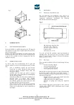
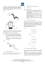
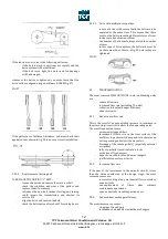
3.3.1
Dimensions of installation room
The air-conditioning unit installation room must be of
sufficient size to permit easy inspection, maintenance and
component
replacement.
Accordingly,
the
following
dimensions are recommended (fig. 3):
-
Heat exchanger extraction side:
min. distance Lb = (B+0,2) m
where B = machine width (m)
-
inspection side:
min. distance Li = 1.2 m
if you do not have the minimum space requirements as
specified above, the units doors can, on request, be fitted
using PVC clamps instead of hinges. In this case the minimum
distance will be Li = 0,7 m.
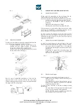
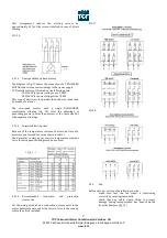
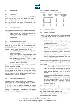
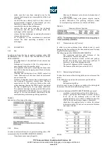
3.3.2
Base frame
The permanent installation of the air-conditioning unit may
be made:
-
directly on the floor (fig. 4a)
-
on a concrete bed (fig. 4b)
-
on a steel section bed (fig. 4c)
-
on a suspended base (fig. 4d)
Both the floor and the beds must be capable of withstanding
the machine weight to within the required safety margins.
The air-conditioning unit must be positioned on a horizontal
surface so as to prevent:
-
damage to the fan motor units caused by uneven
weights on the vibration dampers
-
malfunctioning of the condensate drains
-
difficulty in opening and closing the inspection
doors
The horizontal alignment of the support surface must be
checked with a SPIRIT LEVEL; adjustments may be made
using STEEL SHIMS.


