


TCF Termoventilatori Condizionatori Felsinea Srl
40057 Cadriano di Granarolo Emilia (Bologna), via Giuseppe di Vittorio 5
www.tcf.it
9
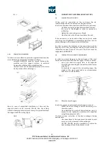
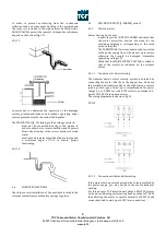
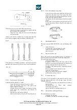
4.6.1.2.1
Selection of the airflow
By operating on the control board (fig. 24) it is possible to
select one of the 31 available speeds:
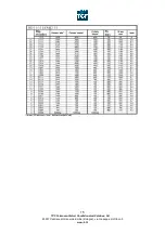
Position the dip-switches from 1 to 5 in the adequate
position in order to obtain the desired air flow. The available
combinations for each fan are indicated in the attachment 1
(page 16).
FIG. 24
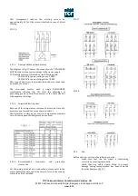
In order to avoid all problems related to current peaks during
the start-up, caused by the condensers charge of the motors
power circuit, we have arranged for a softstop/softstart
(waiting time – consumption = 0,05W) as indicated in the
connection diagram of the control box (fig. 25).
In case this
option is not used, it will be necessary to bridge the
contact between the terminals 3-6.
FIG.25
Closed=softstart
Open=softstop
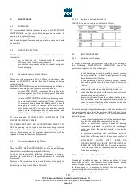
4.6.1.2.2
Alarm on the pressure
This alarm uses the dip-switches from 6 to 8, and allows to
configure an alarm which will inform the user of a variation
in pressure of +25, +50, +75, +100, +150, +200, +250 or +300
Pa in relation to the reference pressure. When these alarms
activate, a LED light will switch on, and the transistor
connected between the connectors G and 2 of the control box
is a conductor.
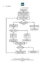
a) how to memorize the reference pressure Pa
ref
:
Pa
ref
corresponds to the ‘starting’ pressure of the fan, that is
the one corresponding to the initial operating point of the
system (i.e. with clean filters). To elaborate the ‘built-in’
alarm you nee to memorize this pressure with the
microprocessor. Memorizing procedure: see attachment 2
page 18.
*********************************************************
**
ATTENTION
**
** The alarm in pressure is fixed only for ONE selected **
** air volume. Changing this air volume modifies the
**
** pre-set alarm – Pa
ref
is no longer correct and has to **
** be re-initialized.
**
*********************************************************
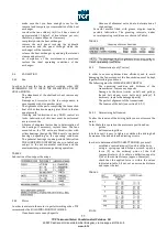
b) how to fix the increase factor
The choice of the increase factor depends on the application.
You may choose one increase out of 8 with the help of the
dip-switches from 6 to 8.
4.7
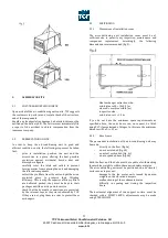
Fan
Before start-up, carry out the following checks:
-
make sure that the fan wheel is functioning
correctly by rotating it manually
4.8
NOISE LEVEL
The computation and control of noise emissions has today
become particularly important, both during the design and
installation phases.
The sound pressure values of our machines are indicated in
our technical catalogues or may be supplied directly by our
Technical Department according to the requested aeraulic
characteristics.
Being therefore aware of the sound emissions produced by
the unit, the designer must make sure that, in treated
environments, maximum values established by current
regulations are not exceeded.
It must however be stressed that every environment has its
own acoustic characteristics, which can considerably affect
the sound pressure values of mechanical ventilation systems.
THE NOISE LEVEL DATA SUPPLIED BY US SHOULD
CONSEQUENTLY BE CONSIDERED AS A CALCULATION BASE
FOR DEEPER CONSIDERATIONS, WHICH WILL TAKE INTO
ACCOUNT THE SYSTEM AND BUILDING STRUCTURE AS A
WHOLE.


