


TCF Termoventilatori Condizionatori Felsinea Srl
40057 Cadriano di Granarolo Emilia (Bologna), via Giuseppe di Vittorio 5
www.tcf.it
12
If the tension is not correct, the following will occur:
-
if the belt is slack, it will wear out rapidly and the
drive system will be inefficient
-
if the belt is too tight, the motor and fan bearings
will be damaged
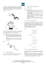
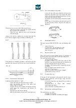
whenever the belts are tightened, you must check that the
drive belts are aligned using an ordinary RULER (fig. 27)
FIG.27
If the pulleys are of different thickness, you must check their
equivalence as shown in fig. 28 to ensure correct installation.
5.4.3.2
Replacement of driving belt
To REPLACE THE DRIVING “V” BELT:
-
loosen the drive and remove the worn-out belt
-
check the condition and wear of the pulleys and
replace them if necessary
-
introduce the new belt without forcing; any forcing
could impair the transmission and shorten its
service life
-
align the drive and tension the belt
-
check the belt tension after about 10 working hours
5.4.3.3
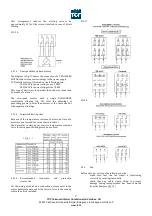
Drive with multiple-race pulleys
-
in case of drives with several belts, the belts must be
replaced at the same time. This means that there
must not be belts presenting different states of wear
in the same transmission system
-
the number of belts must always match the number
of races
-
in this type of drive system, the belt slack must be
on the same side, as shown in fig. 29, before they are
tightened
FIG. 29
5.5
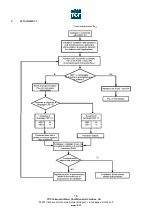
TROUBLESHOOTING
The most common MALFUNCTIONS in air-conditioning units
are:
-
reduced flow rate
-
increased flow rate (excluding TA units)
-
reduction in heat exchanger efficiency
-
abnormal noise
5.5.1
Reduction in flow rate
This is the result of an uncontrolled increase in resistance in
the air moving circuit which alters the fan operating point.
The most frequent causes are:
-
excessively clogged filters
-
formation of frost or ice on the front surface of the
prefilters in particularly damp and cold climates on
units operating entirely with external air
-
blockage of the intake grille(s) (especially external
air intake)
-
fully or partially closed control air locks
-
activation of fire dampers
-
deposits on cell blocks and heat exchangers
-
inefficient fan motor unit drive
5.5.2
Increased flow rate
If the sum of the resistances in the aeraulic circuits is less
than the value considered at the design stage, the most
common causes are:
-
incorrect setting of any mechanical flow controls or
zone air locks
-
non-replacement
of
filters
after
ordinary
maintenance operations
-
open or partially closed inspection doors
5.5.3
Reduced heat exchanger efficiency
The most common causes are:
-
clogging of finned pack
-
formation of air bubbles inside the exchangers