


TCF Termoventilatori Condizionatori Felsinea Srl
40057 Cadriano di Granarolo Emilia (Bologna), via Giuseppe di Vittorio 5
www.tcf.it
1
GENERAL INDEX
0. INTRODUCTION
2
1.
DESCRIPTION OF THE AIR
2
CONDITIONING UNIT
1.1
COMPOSITION
2
1.2
PERMITTED USE
2
2.
CONTROL,PACKING,TRANSPORTATION
2.1
FACTORY INSPECTION OF THE SUPPLY 2
2.2
PACKING
2
2.3
LOADING,TRANSPORT,UNLOADING
2
3.
ASSEMBLY ON SITE
3
3.1
POST-TRANSPORTATION CHECK
3
3.2
PRESERVATION ON SITE
3
3.3
POSITIONING
3
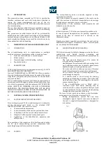
3.3.1
Dimensions of installation room
3
3.3.2
Base frame
3
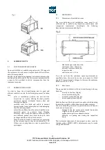
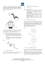
3.3.3
Vibration damping
3
4.
CONNECTION TO SYSTEMS AND START-UP
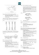
4.1
CONNECTION TO DUCTS
4
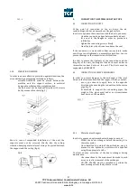
4.2
CONNECTION OF HEAT EXCHANGERS
4
4.2.1
Water heat exchangers
4
4.3
DRAINAGE AND SIPHONING
5
4.4
FILTRATING SECTIONS
6
4.5
FAN-MOTOR UNITS (3-PHASES) series T 6
4.5.1
Electric motors
6
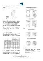
4.5.1.1 Connection for direct starting
6
4.5.1.2 Connection for star-delta starting
6
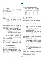
4.5.1.3 Dual speed three-phase motor
7
4.5.1.4 Permitted start-up time
7
4.5.1.5 Recommeded connection and protection 7
accessories
4.5.2
Fan
7
4.5.3.
Transmission
8
4.6
FAN-MOTOR UNITS (1-PHASES) series
TA, PA, TA
8
4.6.1
Electric motors
8
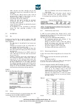
4.6.1.1 3-speed fans series TS and PA
8
4.6.1.2 Self-regulating fans series TA
8
4.6.1.2.1 Selection of the airflow
9
4.6.1.2.2 Alarm on the pressure
9
4.7
Fan
9
4.8
NOISE LEVEL
9
5.
MAINTENANCE
10
5.1
FOREWORD
10
5.2
FILTRATING SECTIONS
10
5.2.1
Reconditionable synthetic filters 10
5.2.2
Non-reconditionable bag filters 10
5.2.2.1 Replacement load loss chart
10
5.3.
HEAT EXCHANGERS
10
5.3.1
Water heat exchangers
10
5.3.2
Extraction of water heat exchangers 10
5.4
FAN SECTION
11
5.4.1
Fan
11
5.4.2
Motor
11
5.4.3
Transmission (only T series)
11
5.4.3.1 Determining belt tension
11
5.4.3.2 Replacement of driving belt
12
5.4.3.3 Drive with multiple-race pulleys 12
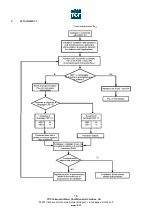
5.5
TROUBLESHOOTING
12
5.5.1
Reduction in flow rate
12
5.5.2
Increase in flow rate
12
5.5.3
Reduced heat exchanger efficiency 12
5.5.4
Abnormal noise level
13
6.
SAFETY
13
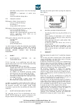
6.1
SAFETY-RELATED FEATURES OF 13
AIR-CONDITIONING UNITS
6.2
SAFETY NOTICES APPLIED TO THE 13
UNITS
6.3
PRACTICAL ACCIDENT-PREVENTION 13
TIPS
7.
WARRANTY
13
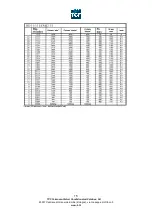
8.
ATTACHMENT 1
14
9.
ATTACHMENT 2
16
10.
ATTACHMENT 3
17


