


TCF Termoventilatori Condizionatori Felsinea Srl
40057 Cadriano di Granarolo Emilia (Bologna), via Giuseppe di Vittorio 5
www.tcf.it
4
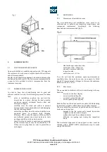
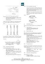
3.3.3
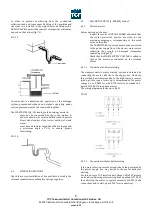
VIBRATION DAMPING
In order to ensure effective protection against vibrations, the
air-conditioning unit must be installed as follows:
-
suitable DAMPERS must be placed between the
machine and the support surface, in material
designed to withstand the weight involved
-
the unit must not be fastened directly with screws
but by means of brackets (fig. 5)
Even in case of suspended installation of the unit, the
supports must not be screwed directly into the ceiling;
vibration damping material must always be placed between
the support and the ceiling (fig. 6).
4.
CONNECTION TO SYSTEMS AND START UPS
4.1
CONNECTION TO DUCTS
At the point of connection to the air ducts, the air-
conditioning units have a smooth or a flanged surface.
In order to optimise the connection with the ducts, you must:
-
clean the connection edges between duct and unit
-
fit a seal to the flanges in order to prevent air
infiltration
-
tighten the connecting screws firmly
-
treat the joint with silicone to enhance the seal
If the connection is made with rubber canvas joints, make
sure they are not tightened on assembly completion, so as to
prevent damage or the transmission of vibrations.
In order to ensure the tightness of the connections and the
integrity of the unit, the weight of the ducts must under no
circumstances bear down on the unit. The ducts must be
supported by BRACKETS.
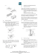
4.2
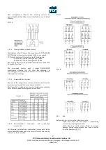
CONNECTION OF HEAT EXCHANGERS
In order to prevent damage to the exchanger at the joint
between the steel manifold and the copper circuits, you must:
-
use a pipe wrench to apply force in the opposite
direction when making the connection to the mains
pipe (fig. 7)
-
fit brackets to support the connecting pipes; the
weight of the pipes must under no circumstances
bear down on the manifold.
4.3.1
Water heat exchangers
In order to ensure an optimum heat exchange, you must:
-
WASH the heat exchanger before connecting it to
the water mains
-
Once installed in a state-of-the-art fashion, any air
present in the hydraulic circuit must be expelled
using the appropriate valve
To allow an easy extraction of the heat exchanger during
maintenance:
-
the connections to the mains must be made in such
a way as to allow removal of the exchanger
-
ON-OFF VALVES must be installed to exclude the
heat exchanger from the hydraulic circuit


