background image


TCF Termoventilatori Condizionatori Felsinea  Srl 

40057 Cadriano di Granarolo Emilia (Bologna), via Giuseppe di Vittorio 5 

www.tcf.it 

17 


10. 

ATTACHMENT 3

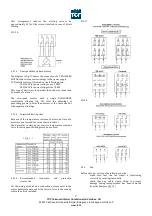
: Characteristics of input/output signals 

 
Attention:  all  connections  not  compliant  with  the  specifications  may  damage  the  circuit  irreversibly.  This  might  redefine  the 
warranty conditions. 
 
Cables and connections 
 

1.


Control cables 

All  the  connections  must  be  carried  out  in  strict  compliance  with  the  wiring  diagram  indicated  in  this  document.  The 
connection cables must be shielded, of maximum  section 0,5 mm

2

.  The mass braid of the cable must be connected to a G 

connector of the control box. In order to prevent all interferences, we recommend to separate the cable of all the external 
sources of disturbance. Use one of the cables of the following list (or equivalent): 


2.


Connecting cables between the power box and the control box 

UTP cable /  category 5 / 8 threads. Maximum length = 100 m 
RJ45 connectors: no particular specification 

 
External contacts K’1 and K’2: 
 

Contacts free from potentials  


Mx. impedence : 10 KΩ 

 
12V feed available on output: 
 

Output voltage: 12 Vdc ±2% (between the connector G and 7) 


Max. available I:  80 mA 

 
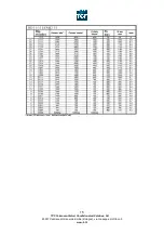
Output signal: ‘feedback’ of the rate 
 

Analogic signal between the connectors G and 8 of the control circuit corresponding to the airflow of the fan 


Minimum impedence: 10 MΩ. Tolerance: ±5% 


Example: If you measure 2,38V within G and 8 on a DD 9-9 ECMd2, the airflow of the fan is (2900*(2,38/4,65)) m

3

h 1485. 


Summary of Contents for T Series

Page 1: ...INSTRUCTIONS OPERATION AND MAINTENANCE MANUAL AIR CONDITIONING UNITS SERIES T TS TA PA...

Page 2: ...ion and protection 7 accessories 4 5 2 Fan 7 4 5 3 Transmission 8 4 6 FAN MOTOR UNITS 1 PHASES series TA PA TA 8 4 6 1 Electric motors 8 4 6 1 1 3 speed fans series TS and PA 8 4 6 1 2 Self regulating...

Page 3: ...e various safety rules in force Integrity of all the system s component parts Application of the identification operation and safety notices On completion of the inspection the Chief Inspector applies...

Page 4: ...t the hydraulic connections are protected by the relevant caps as they were delivered by TCF If they are not plug them in order to protect them exchangers 3 3 POSITIONING 3 3 1 Dimensions of installat...

Page 5: ...o enhance the seal If the connection is made with rubber canvas joints make sure they are not tightened on assembly completion so as to prevent damage or the transmission of vibrations In order to ens...

Page 6: ...may be provided fig 10 This configuration must be determined at the design stage and not during installation since on obvious reduction in efficiency will result if a heat exchanger sized for reverse...

Page 7: ...motors Before starting up the unit inspect the motor CONTROL BOARD and check that the motor protection devices are sized for the maximum amperage corresponding to the rated value on the plate The TERM...

Page 8: ...AHLANDER commutable winding fig 18 offer the advantage of generating greater power than motors of the same size but with separate windings 4 5 1 4 Permitted start up time Because of the temperature in...

Page 9: ...e connected to the power supply line of the electric motors since otherwise they would be damaged irreparably Check that the MAINS SUPPLY VOLTAGE is suited to that of the motors as indicated on the re...

Page 10: ...e initial operating point of the system i e with clean filters To elaborate the built in alarm you nee to memorize this pressure with the microprocessor Memorizing procedure see attachment 2 page 18 A...

Page 11: ...phragm as long as possible the condition of the prefilters must be carefully monitored Moreover TCF recommends to check the state of the gaskets of the frame and the springs every week to prevent air...

Page 12: ...ject to the environmental conditions and the maximum temperature range during operation TABLE 3 Lubrication of fan support bearings 5 4 2 Motor In order to maintain the motor in perfect working order...

Page 13: ...mber of belts must always match the number of races in this type of drive system the belt slack must be on the same side as shown in fig 29 before they are tightened FIG 29 5 5 TROUBLESHOOTING The mos...

Page 14: ...anger connected with moving parts and warning him to disconnect the system power before opening the inspection doors fig 30 FIG 30 6 3 PRACTICAL ACCIDENT PREVENTION TIPS Open the inspection doors only...

Page 15: ...TCF Termoventilatori Condizionatori Felsinea Srl 40057 Cadriano di Granarolo Emilia Bologna via Giuseppe di Vittorio 5 www tcf it 14 8 ATTACHMENT 1...

Page 16: ...TCF Termoventilatori Condizionatori Felsinea Srl 40057 Cadriano di Granarolo Emilia Bologna via Giuseppe di Vittorio 5 www tcf it 15...

Page 17: ...TCF Termoventilatori Condizionatori Felsinea Srl 40057 Cadriano di Granarolo Emilia Bologna via Giuseppe di Vittorio 5 www tcf it 16 9 ATTACHMENT 2...

Page 18: ...control box In order to prevent all interferences we recommend to separate the cable of all the external sources of disturbance Use one of the cables of the following list or equivalent 2 Connecting...

Page 19: ...TCF Termoventilatori Condizionatori Felsinea Srl 40057 Cadriano di Granarolo Emilia Bologna via Giuseppe di Vittorio 5 www tcf it 18...

Reviews: