


Maintenance, Service, and Repair
Tires and Wheels
Page 5
Explosion Hazard. Fully deflate the tire before attempting to remove
the tire from the wheel. Do not over inflate the tire when seating the
bead. Failure to deflate the tire or over inflating the tire to seat the
bead may cause explosive failure of the tire resulting in severe bodily
injury or death.
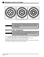
REPLACE THE TIRE (PNEUMATIC)
NOTE; To replace the tire, the tire/wheel assembly must be removed from the vehicle. Refer to
Replace
the Tire/Wheel
section for information on removing the tire/wheel assembly.
Tire replacement should only be performed by personnel trained in tire replacement.
The tire replacement procedure will be unique to the type of replacement equipment being used. Refer to
the instructions provided with your equipment.
Always use a new valve stem when replacing a tire.
1. Remove the tire from the wheel.
2. Cut the old valve stem off of the wheel.
3. Remove the valve stem cap from the new valve stem.
4. Lubricate the valve stem with liquid soap.
5. Install a new valve stem using a valve stem tool.
NOTE: The valve stem tool is available at most auto repair shops.
6. Install the tire onto the wheel following the instructions provided with your tire replacement equipment.
7. Inflate the tire to the proper pressure and check for leaks.
8. Install the valve stem cap.
Summary of Contents for ET-015-00
Page 2: ......
Page 14: ...TAYLOR DUNN...
Page 28: ...TAYLOR DUNN...
Page 48: ...Maintenance Service and Repair Steering Page 12 Exploded View of Steering Gear...
Page 60: ...Maintenance Service and Repair F2 F3 Transmission Page 12 EXPLODED VIEW...
Page 71: ...Maintenance Service and Repair Brakes Page 11 Rear Brake left side shown...
Page 72: ...TAYLOR DUNN...
Page 80: ...TAYLOR DUNN...
Page 90: ...TAYLOR DUNN...
Page 94: ...TAYLOR DUNN...
Page 100: ...TAYLOR DUNN...
Page 114: ...TAYLOR DUNN...
Page 116: ...TAYLOR DUNN...
Page 130: ...Illustrated Parts Parts Page 14 Rear Axle Axle tube 4 5 6 7 3 2 Rear Brakes...
Page 132: ...Illustrated Parts Parts Page 16 Rear Suspension 1 2 3 4 5 6 7 8 9 10 11 12 13 14 Drive Shaft...
Page 134: ...Illustrated Parts Parts Page 18 Motor direct drive Motor Mount direct drive...
Page 142: ...Illustrated Parts Parts Page 26 Instrument Panel dash...
Page 144: ...Illustrated Parts Parts Page 28 Speed Control Panel 1 2 3 4 5 6 7 8 9 10 11 12 4...
Page 152: ...Illustrated Parts Parts Page 36 Charger 2 1 15 12 11 4 3 5 8 10 6 7 9 13 14 16...